
Displacement detection device for a portable apparatus

a detection device and portable technology, applied in the direction of acceleration measurement in multiple dimensions, acceleration measurement using interia forces, devices characerised by mechanical means, etc., can solve the problems of inability of the described circuit to adapt automatically to the change of posture of the user, inability to trigger undesirable activation events, inability to involuntary movements, etc., to achieve the effect of solving the problem of inability to involuntary movement and triggering undesirable activation events

Active Publication Date: 2010-03-02
STMICROELECTRONICS SRL
View PDF7 Cites 103 Cited by
  • Summary
  • Abstract
  • Description
  • Claims
  • Application Information

AI Technical Summary

Benefits of technology

[0022]The disclosed embodiments of the present invention provide a displacement detection device that will enable the drawbacks described above to be overcome and, in particular, that will enable detection operations to be made independent of the initial position assumed by the portable apparatus incorporating the detection device.

Problems solved by technology

Furthermore, this problem is aggravated by the fact that each user has a personal way of holding a portable apparatus, and the differences increase, for example, between right-handed users and left-handed users.
In fact, the described circuit is not able to adapt automatically to the change of posture of the user, including for example the inevitable (in so far as involuntary) movements of the wrist that cause a variation in the portable apparatus orientation.
Furthermore, in the worst case (i.e., when said involuntary movements are greater than the acceleration threshold), the involuntary movements could trigger an undesirable activation event.
It is, consequently, evident that a solution of this type actually makes unnatural the use of functions activated by movement, which instead should simplify the man-machine interface.
This solution is, however, far from practicable, unless high computing power is available.

Method used


Image

  • Displacement detection device for a portable apparatus
  • Displacement detection device for a portable apparatus
  • Displacement detection device for a portable apparatus

Examples


Embodiment Construction

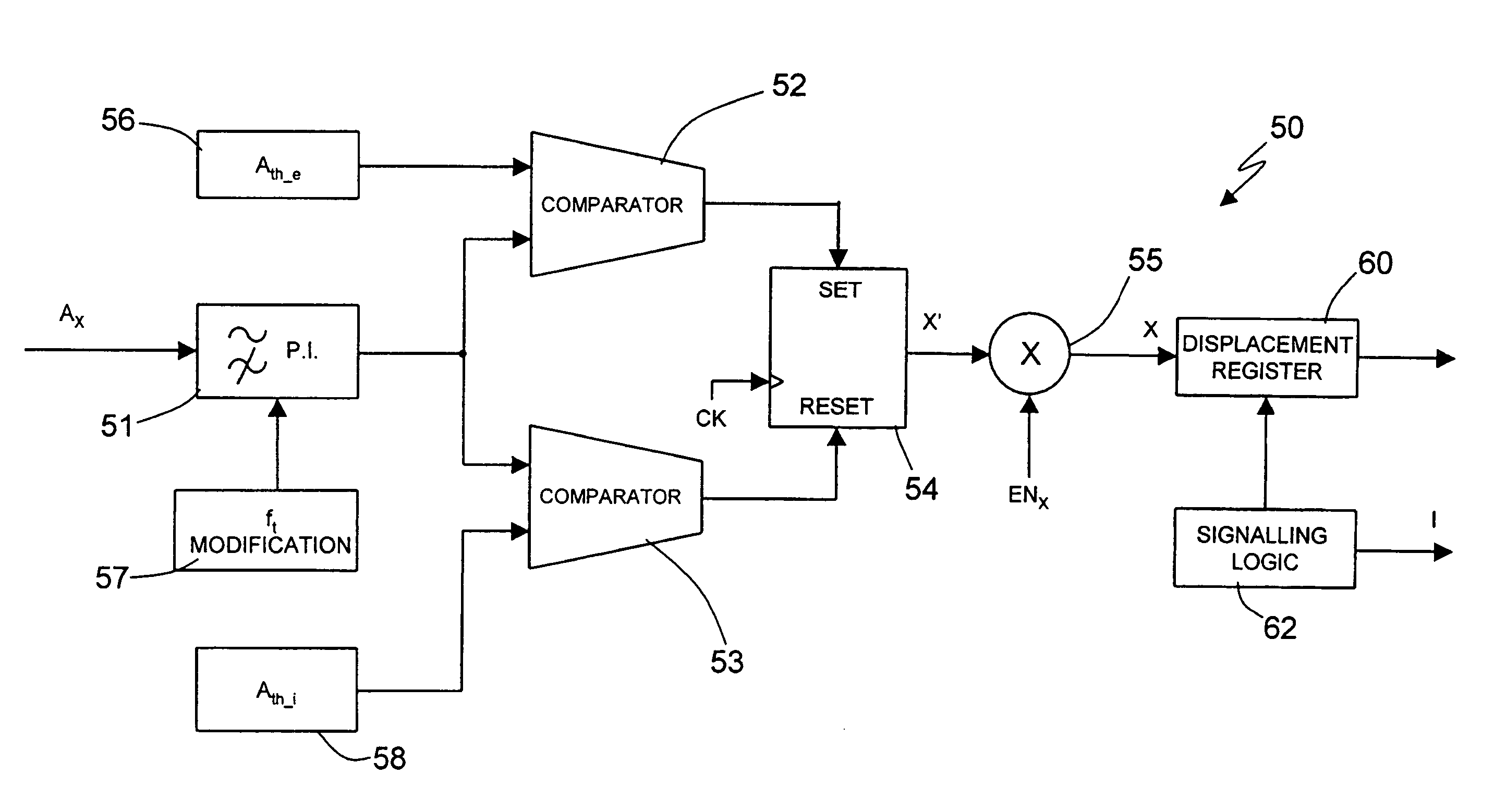
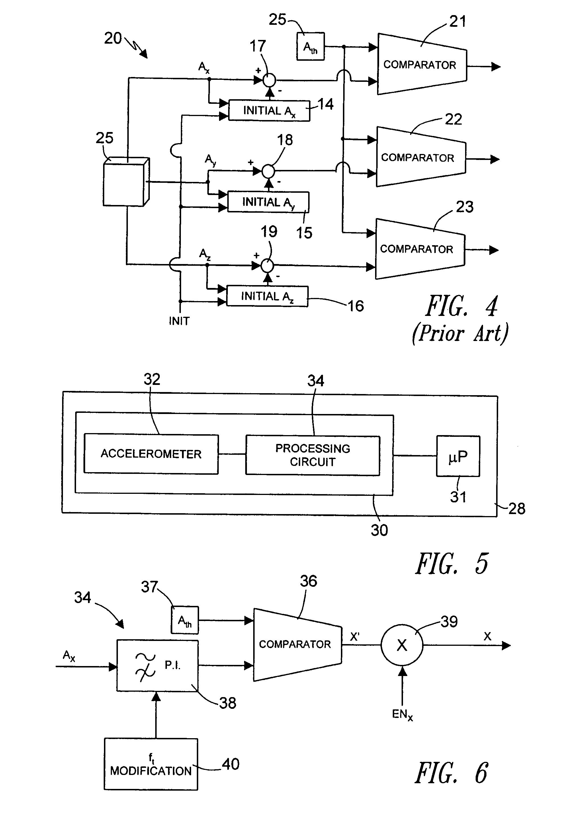
[0045]FIG. 5 is a schematic illustration of a portable apparatus 28 provided with a displacement detection device 30 and with a microprocessor 31 in accordance with one embodiment of the invention. The displacement detection device 30 includes an accelerometer 32 of a linear type, and a processing circuit 34. In particular, the accelerometer 32 and the processing circuit 34 are integrated in a single chip.

[0046]The accelerometer 32 is of a known type. In one embodiment, it is a MEMS device made with the semiconductor technology and has three axes of detection x, y and z so as to generate three acceleration signals Ax, Ay and Az. Each acceleration signal is correlated to the acceleration detected along a respective axis of detection. For example, the accelerometer 32 can be realized as described in “A low-g 3 axis digital output accelerometer for emerging automotive applications”, B. Vigna, et al., AMAA 2004.

[0047]The processing circuit 34 receives at input the acceleration signals A...


PUM


Abstract

In a displacement detection device, an acceleration sensor generates at least a first acceleration signal relating to an axis of detection, and a displacement detection circuit is connected to the acceleration sensor has a comparator stage for comparing the acceleration signal with a programmable acceleration threshold and generates a displacement-detection signal. A high-pass filter is arranged between the acceleration sensor and the comparator stage so as to reduce a DC component of the acceleration signal. The cut-off frequency of the high-pass filter is modified according to the type of displacements that are to be detected.

Description

BACKGROUND OF THE INVENTION[0001]1. Field of the Invention[0002]The present invention relates to a displacement detection device for a portable apparatus and, more particularly, to a device that simplifies the user interface of the portable apparatus.[0003]2. Description of the Related Art[0004]As is known, in the last few years, with the increasing use of portable electronic devices (such as laptops, Personal Data Assistants (PDAs), digital audio players, cellphones, digital video cameras, and the like), the need has arisen to simplify the use of such devices and, in particular, to simplify the user interface. In this regard, of particular interest is the possibility of activating given functions or programs of the portable devices with a simple movement imparted thereon by the user. Consider, for example, navigation within a list of options or an address book of a cellphone by simply tilting it or moving it in the direction in which is it is desired to scroll the list or the addre...

Claims


Application Information

Patent Timeline
Patent Type & Authority Patents(United States)
IPC IPC(8): G01P15/18
CPCG01P15/0891G01P15/18G11B19/04
Inventor TRONCONI, MICHELECHIESA, ENRICOPASOLINI, FABIO
Owner STMICROELECTRONICS SRL
Learn More