Ultrasonic actuator, driving method of the ultrasonic actuator, lens driver, and portable device
a technology of ultrasonic actuators and ultrasonic actuators, which is applied in the direction of instruments, printers, cameras, etc., can solve the problems of affecting the characteristic high-definition operation, affecting the operation, and affecting the operation stability, so as to achieve stably driven, the effect of loss of synchronization and stabilization
- Summary
- Abstract
- Description
- Claims
- Application Information
AI Technical Summary
Benefits of technology
Problems solved by technology
Method used
Image


Examples
first embodiment
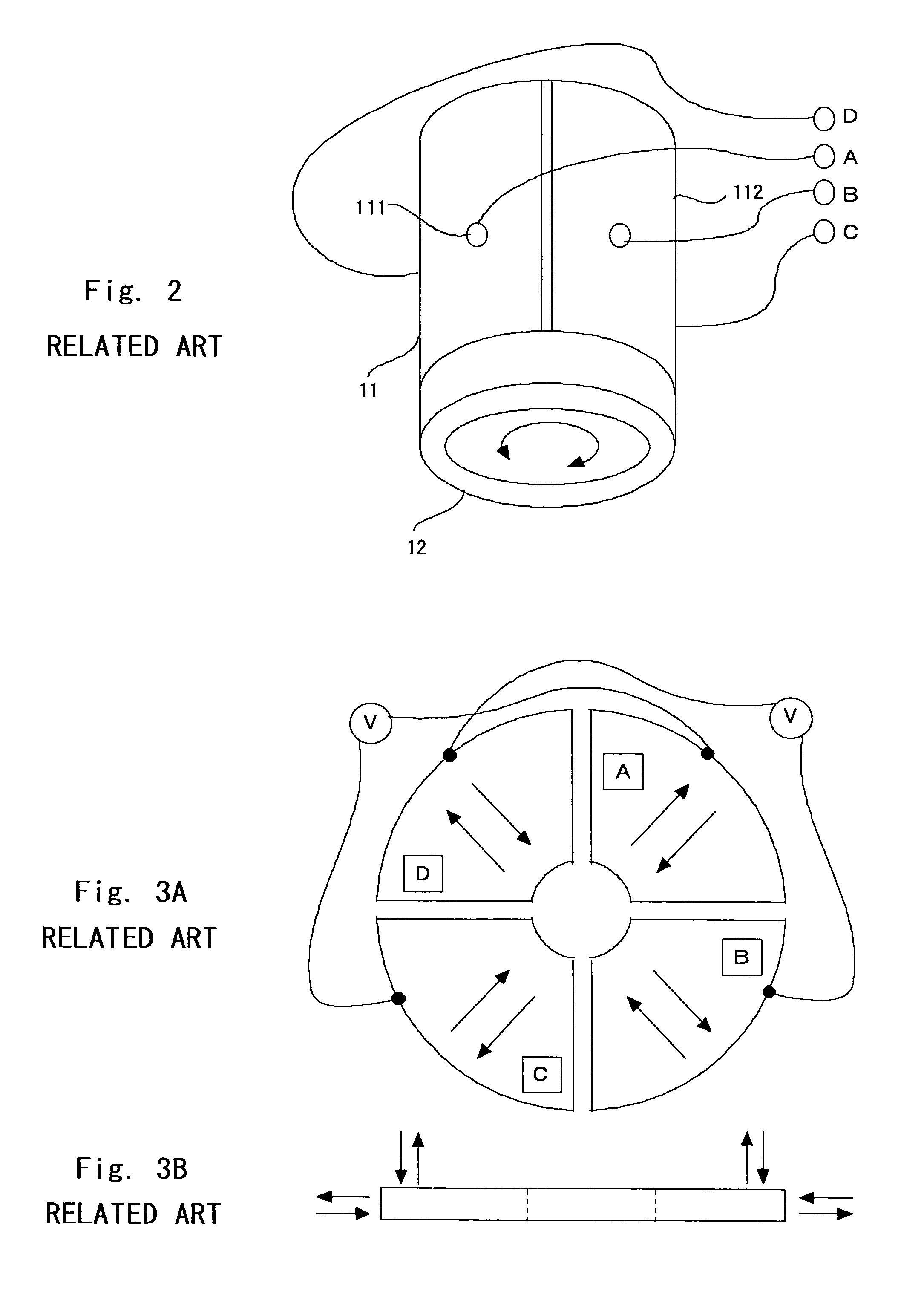
[0073]A basic structure of an ultrasonic actuator according to a first embodiment of the present invention is the same as that of a conventional ultrasonic motor as shown in FIG. 2 and FIGS. 3A and 3B. A feature of the ultrasonic actuator of this embodiment resides in a driving signal.
[0074]FIG. 8 is a signal waveform diagram of driving signals (hereinafter referred to as “reference driving signals”) for rotating the ultrasonic motor at a normal speed, that is, at a non-decreased speed. As shown in FIG. 8, at the normal speed, four-phase pulse driving signals A, B, C, and D are applied to electrodes 111, 112, 113, and 114 of the ultrasonic motor respectively. The driving signals A, B, C, and D each includes plural pulse trains and have a fixed frequency determined based on a resonance point of a piezoelectric element. A pulse width and pulse voltage of each pulse in each driving signal are constant. As described in the related art, a rotor 12 is brought into close contact with an up...
second embodiment
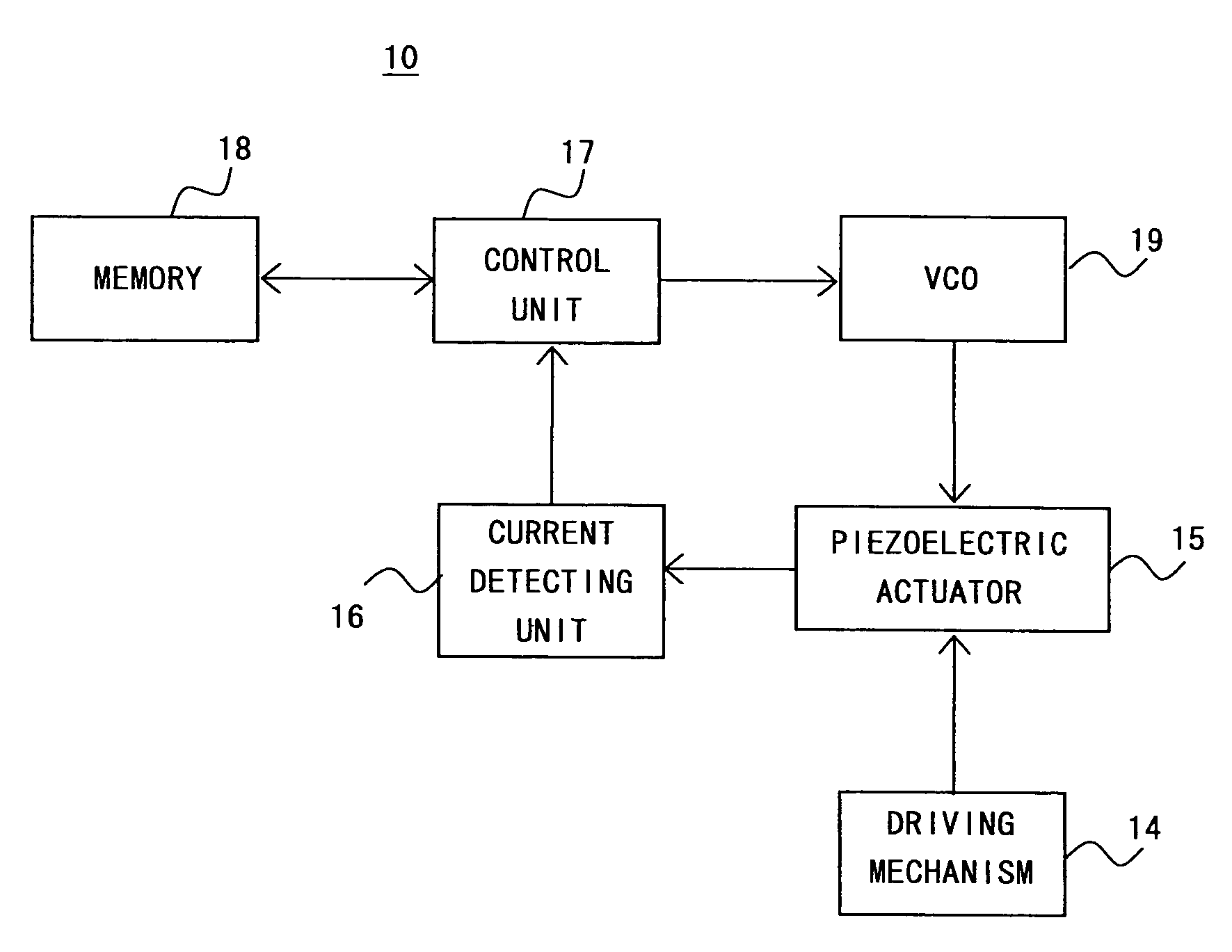
[0083]A driver of an ultrasonic actuator according to a second embodiment of the present invention drives the ultrasonic actuator while the largest drive current amount for the piezoelectric actuator of the stator 11 is kept within a frequency range higher than a resonance frequency (demodulation frequency) at which driving is started. To be specific, the driver gradually raises a frequency of a driving signal to the demodulation frequency to start driving the ultrasonic actuator and drives the ultrasonic actuator within a frequency range higher than the demodulation frequency.
[0084]This embodiment describes a piezoelectric motor as a preferred example of the ultrasonic actuator. However, the present invention is not limited thereto, and various actuators can be obtained by changing a mechanism of transmitting driving force.
[0085]Referring to FIG. 14, the structure of a driver of piezoelectric motor of this embodiment is described first. FIG. 14 is a block diagram of a structural ex...
third embodiment
[0103]An actuator according to a third embodiment of the present invention moves two members using one piezoelectric element. In particular, these two members can be individually driven. This embodiment describes a lens driver to which the actuator is applied by citing a digital camera as a preferred example of the portable device of this embodiment. Further, a preferred example of the lens driver of this embodiment is described taking a lens driver of a camera for individually driving the zoom lens and the autofocus lens as an example. Incidentally, in the following description, the term “zoom” is also abbreviated to “ZM”, and the term “autofocus” is also abbreviated to “AF”.
[0104]Hereinafter, the digital camera of this embodiment is described with reference to the accompanying drawings.
[0105]Referring to FIG. 17, the schematic structure of a digital camera of the third embodiment is described. FIG. 17 is a block diagram illustrating functions of the digital camera of the third emb...
PUM
 Abstract
Description
Claims
Application Information
 - R&D
- Intellectual Property
- Life Sciences
- Materials
- Tech Scout
- Unparalleled Data Quality
- Higher Quality Content
- 60% Fewer Hallucinations
Browse by: Latest US Patents, China's latest patents, Technical Efficacy Thesaurus, Application Domain, Technology Topic, Popular Technical Reports.
© 2025 PatSnap. All rights reserved.Legal|Privacy policy|Modern Slavery Act Transparency Statement|Sitemap|About US| Contact US: help@patsnap.com