Armature and motor
a technology of armature and motor, which is applied in the direction of windings, transformer/inductance details, transformer/inductance coils/windings/connections, etc., can solve the problems of disadvantageous increase in axial size of armature core, and disadvantageous increase in costs, so as to reduce the axial size of armature and facilitate winding operation.
- Summary
- Abstract
- Description
- Claims
- Application Information
AI Technical Summary
Benefits of technology
Problems solved by technology
Method used
Image

Examples
first embodiment
[0051]A structure of an armature 10 according to a first embodiment of the present invention will be described.
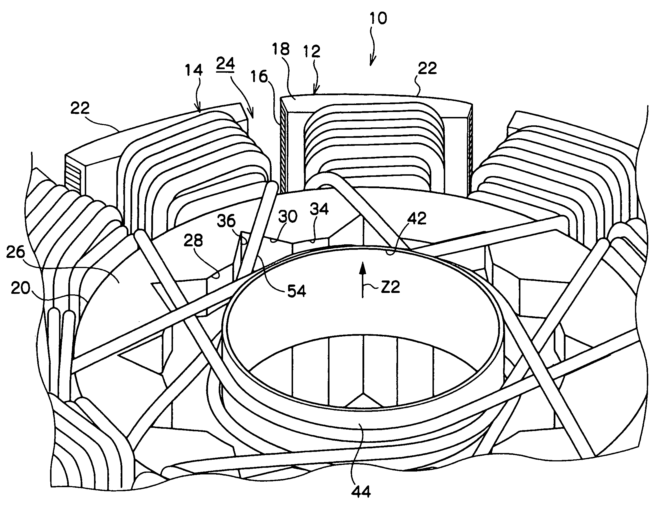
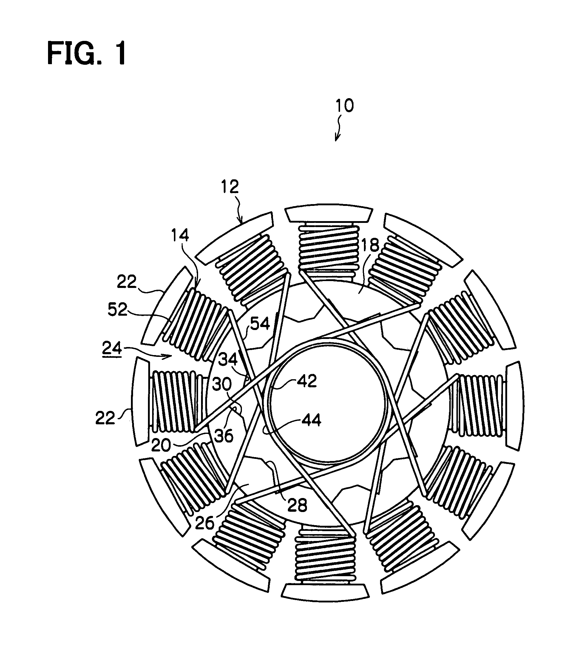
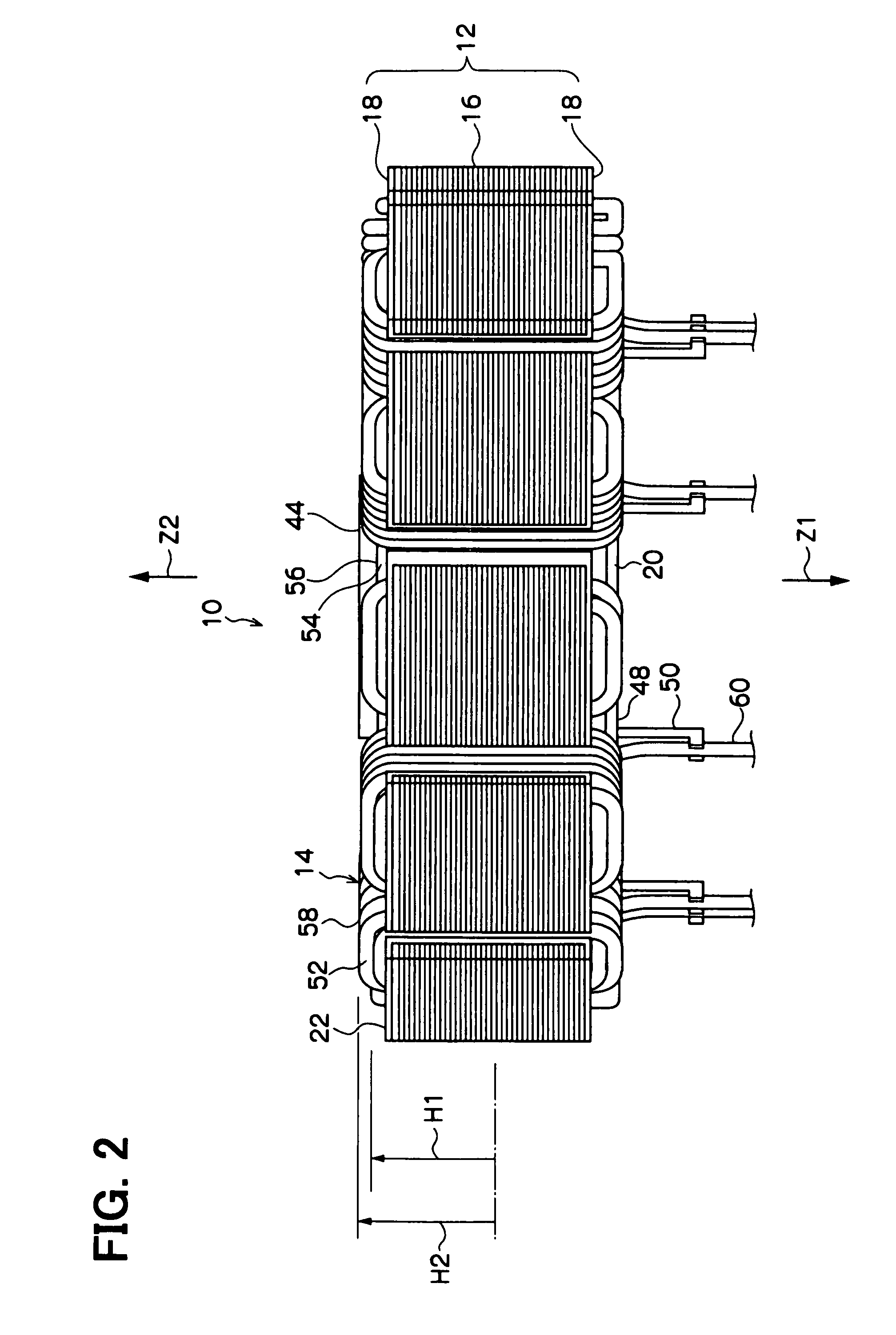
[0052]FIGS. 1 to 5 show the structure of the armature 10 according to the first embodiment of the present invention. FIG. 1 is a plan view of the armature 10. FIG. 2 is a side view of the armature 10. FIG. 3 is an enlarged partial perspective view of the armature 10 seen from a second axial side (Z2 side). FIG. 4 is an enlarged partial plan view of the armature 10. FIG. 5 is a perspective view of the armature 10 seen from a first axial side (Z1 side).
[0053]The armature 10 according to the first embodiment of the present invention shown in the above-described drawings is used in, for example, a fan motor 70. The armature 10 includes a stator core 12 and a plurality of windings 14.
[0054]As shown in FIG. 2, the stator core 12 includes a laminated core 16 and two dielectric insulators 18. The laminated core 16 includes a plurality of core sheets (thin iron plates), which are ax...
second embodiment
[0098]A structure of a fan motor 70 according to a second embodiment of the present invention will be described.
[0099]FIGS. 14 to 19 show the structure of the fan motor 70 according to the second embodiment of the present invention. The fan motor 70 shown in these drawings is for cooling the radiator of the vehicle. As shown in FIG. 14, the fan motor 70 includes a stator housing (also referred to as a centerpiece) 112, a rotor 114, a fan 116, an armature (stator) 118 and a control circuit device 120.
[0100]The stator housing 112 is made of an iron material and includes a main body support portion 122. The main body support portion 122 is axially placed between circuit power supply portions (connection terminal plates or conductors) 168 of the circuit device 120 and the armature 118. As shown in FIGS. 14 and 17, the main body support portion 122 includes a plurality of receiving holes 124, which are arranged one after another in a circumferential direction and penetrate through the ma...
third embodiment
[0133]A structure of a fan motor 70 according to a third embodiment of the present invention will be described.
[0134]FIGS. 23 to 28B show the structure of the fan motor 70 according to the third embodiment of the present invention. The fan motor 70 of the third embodiment of the present invention includes an armature 218 in place of the armature 118 of the fan motor 70 of the second embodiment. Thus, in the third embodiment of the present invention, the armature 218 will be described in detail, and the other parts of the fan motor 70 other than the armature 218 will be indicated by the same reference numerals as those of the second embodiment and will not be described further.
[0135]In the fan motor 70 of the third embodiment of the present invention, as shown in FIG. 23, the armature 218 includes a laminated core 244, a plurality (two in this instance) of insulators 246 and a plurality of windings 250. As shown in FIG. 25, the laminated core 244 includes a first core sheet assembly ...
PUM
 Abstract
Description
Claims
Application Information
 - R&D
- Intellectual Property
- Life Sciences
- Materials
- Tech Scout
- Unparalleled Data Quality
- Higher Quality Content
- 60% Fewer Hallucinations
Browse by: Latest US Patents, China's latest patents, Technical Efficacy Thesaurus, Application Domain, Technology Topic, Popular Technical Reports.
© 2025 PatSnap. All rights reserved.Legal|Privacy policy|Modern Slavery Act Transparency Statement|Sitemap|About US| Contact US: help@patsnap.com