
Power board and plug-in lighting module

a technology of power board and plug-in lighting, which is applied in the direction of lighting support devices, coupling device connections, instruments, etc., can solve the problems of limited light, inability to extend the interconnection board to create a homogeneous lit surface, and the inability of modules to be assembled to form a larger homogeneous lit surface without additional optics

Inactive Publication Date: 2010-02-23
SIGNIFY HLDG BV
View PDF26 Cites 69 Cited by
  • Summary
  • Abstract
  • Description
  • Claims
  • Application Information

AI Technical Summary

Problems solved by technology

Despite ongoing improvements in components and apparatus design, requirements for different shapes and forms still necessitate the assembly of tailor made components that entail a number of economic limitations.
In addition, because of the employed tri-color LEDs and the color mixing control, the emitted light is limited to a range of orange colors including a pure saturated green and a pure saturated red.
The interconnection boards cannot be extended to create a homogeneous lit surface without leaving a substantial gap in between the LEDs, and can only be extended by means of a particular wiring system.
The PCBs are pre-grooved such that custom sized large area LED modules can be easily truncated however the modules cannot be assembled to form a larger homogeneously lit surface without any additional optics.
However, only issues of electrical connectivity but no mechanical or thermal contact management are addressed and devices can only be placed at predetermined locations.
While there are many lighting systems that can achieve a homogeneously lit surface impression, the design of these systems is either monolithic or involves a number of custom made components that can require elaborate assembly procedures.

Method used


Image

  • Power board and plug-in lighting module
  • Power board and plug-in lighting module
  • Power board and plug-in lighting module

Examples


Embodiment Construction

Definitions

[0024]The term “light-emitting element” is used to define any device that emits radiation in any region or combination of regions of the electromagnetic spectrum for example, the visible region, infrared and / or ultraviolet region, when activated by applying a potential difference across it or passing a current through it, for example. Therefore a light-emitting element can have monochromatic, quasi-monochromatic, polychromatic or broadband spectral emission characteristics. Examples of light-emitting elements include semiconductor, organic, or polymer / polymeric light-emitting diodes, optically pumped phosphor coated light-emitting diodes, optically pumped nano-crystal light-emitting diodes or any other similar light-emitting devices as would be readily understood by a worker skilled in the art. Furthermore, the term light-emitting element is used to define the specific device that emits the radiation, for example a LED die, and can equally be used to define a combination ...


PUM


Abstract

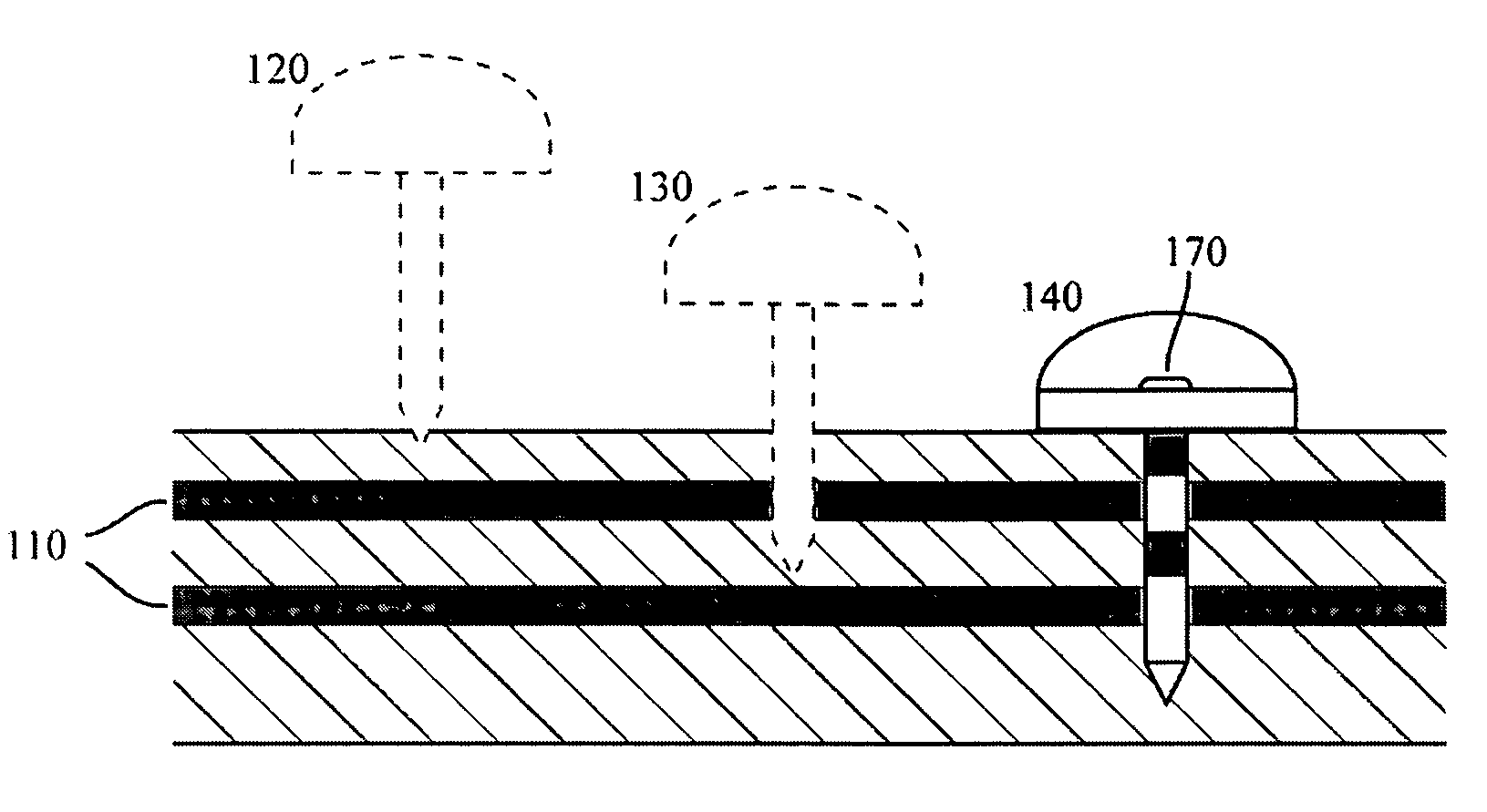
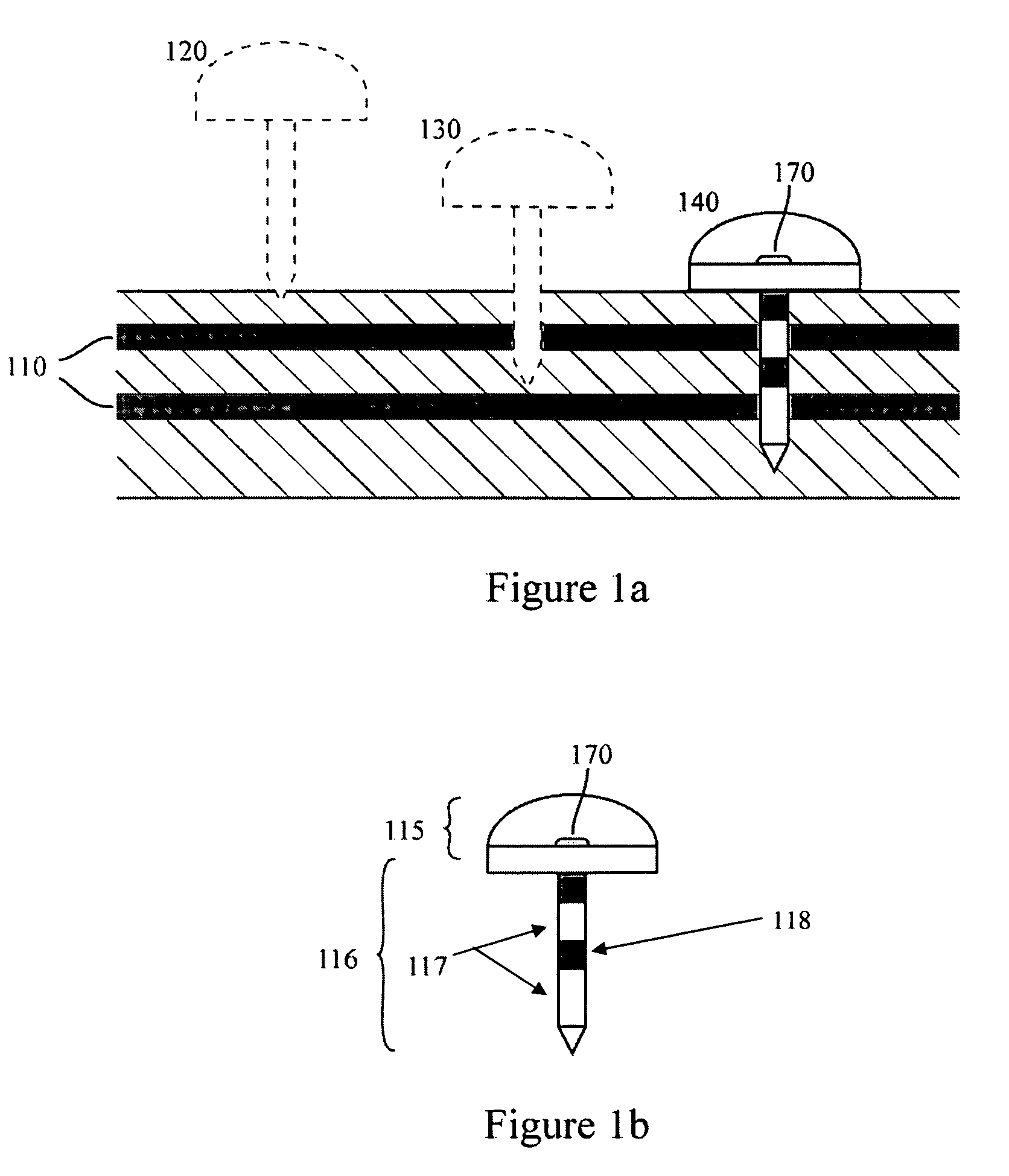
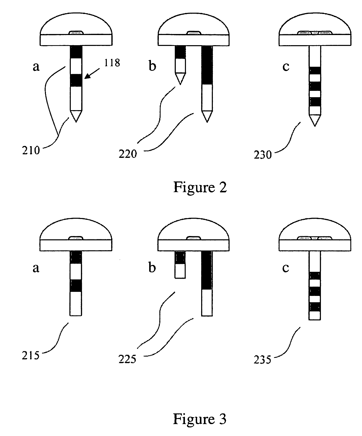
The present invention provides a modular panel lighting apparatus comprising a multi layer power board and one or more lighting modules. The power board is a compound structure of one or more electrically conductive layers which are separated by one or more electrically insulating layers. The power board is configured to receive one or more lighting modules and can provide electrical, mechanical and thermal function adequate to meet a desired functionality of the lighting apparatus. A lighting module comprises one or more light-emitting elements operatively attached to a connector element that has one or more electrical contact portions. By inserting the connector element into the power board, the lighting module can be mounted anywhere on the face of the power board. When appropriately inserted into the power board, the one or more electrical contact portions of the connector element can establish selective electrical contact with the conductive layers of the power board and can secure the lighting module in place.

Description

[0001]This application claims Priority from Provisional application 60 / 699,988 filed on Jul. 14, 2005.FIELD OF THE INVENTION[0002]The present invention pertains to the field of lighting systems and in particular to panel lighting systems incorporating light-emitting elements.BACKGROUND[0003]Advances in the development and improvements of the luminous flux of light-emitting devices such as semiconductor, organic or polymer light-emitting diodes (LEDs) have made these devices suitable for use in general illumination applications, including architectural, entertainment, and roadway lighting, for example. As such, LEDs are becoming increasingly competitive with light sources such as incandescent, fluorescent, and high-intensity discharge lamps.[0004]Light-emitting diodes offer a number of advantages and are generally chosen for their ruggedness, long lifetime, high efficiency, low voltage requirements, and above all the possibility to control the color and intensity of the emitted light...

Claims


Application Information

Patent Timeline
Patent Type & Authority Patents(United States)
IPC IPC(8): H01R33/00
CPCF21V21/0824F21V23/06G09F13/00H01R4/2404H05K3/326F21V21/002F21V19/001H05K2203/1189F21Y2101/02H01R24/58H01R2103/00H05K1/0298H05K3/308H05K2201/10106H05K2201/1059F21Y2115/10H01R4/2406
Inventor MATHESON, GEORGE E.
Owner SIGNIFY HLDG BV
Learn More