
Rotating window

a rotating window and rotating technology, applied in the field of rotating windows, can solve the problems of affecting and achieve the effect of improving the safety of people and objects and reducing the blockage of viewing the rotating window

Active Publication Date: 2010-02-23
YEH TZU YUAN
View PDF9 Cites 5 Cited by
  • Summary
  • Abstract
  • Description
  • Claims
  • Application Information

AI Technical Summary

Benefits of technology

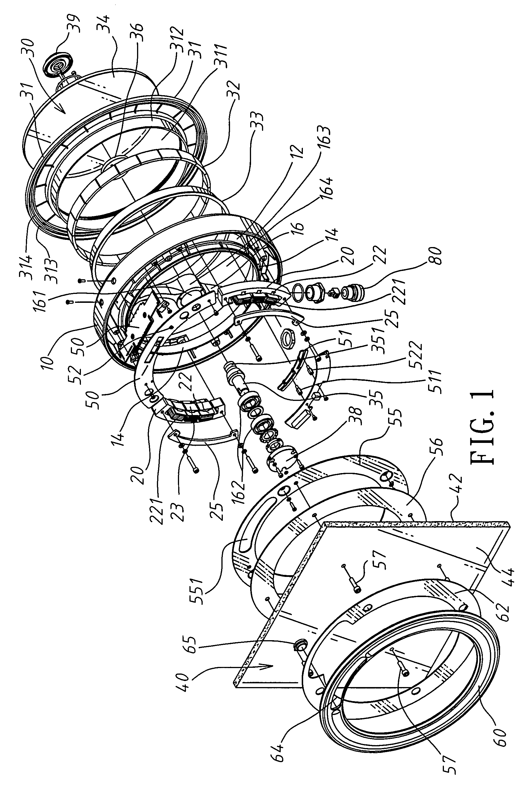
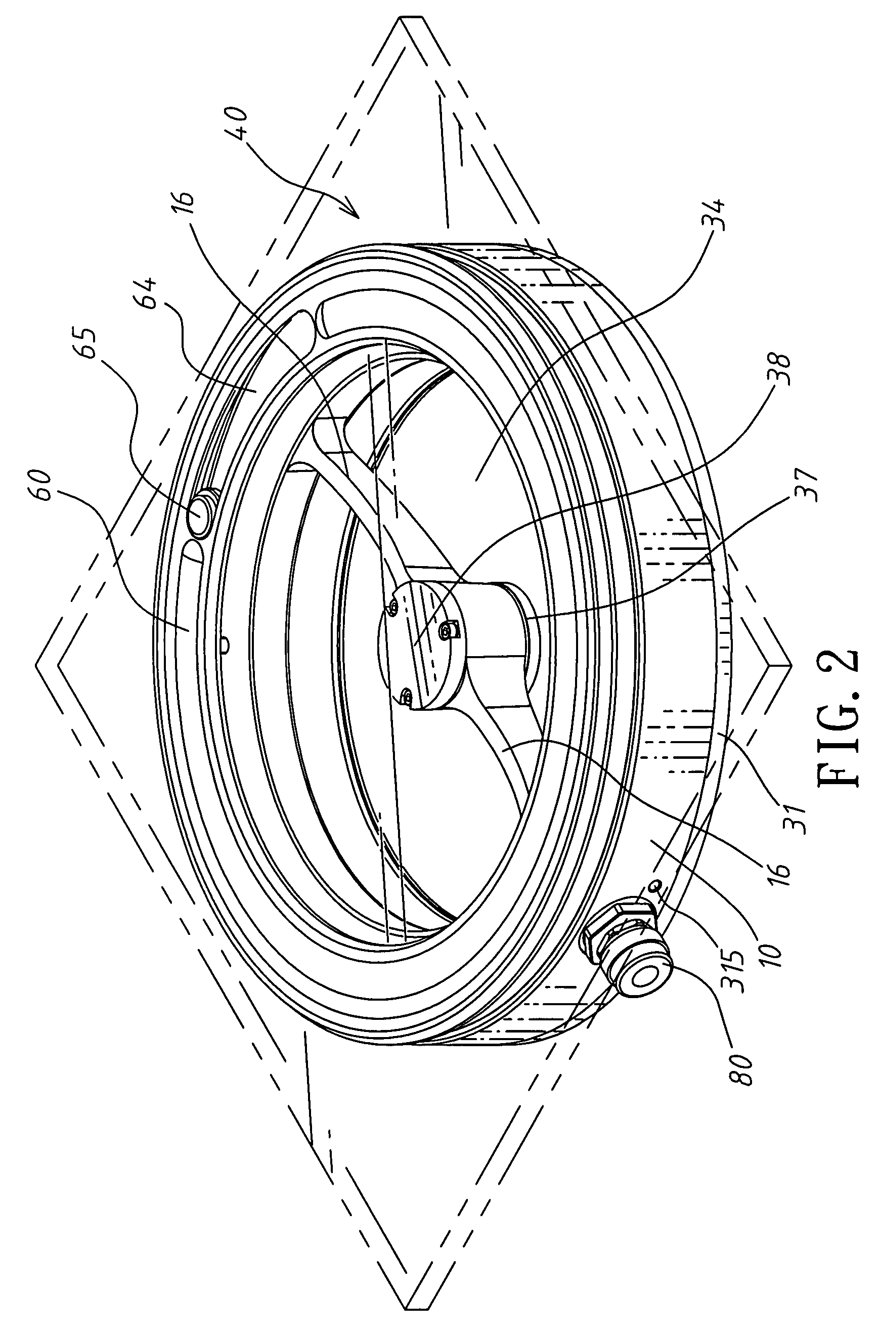
[0009]The primary object of present invention is to provide a rotating window which is provided with broader transparent area, such that blockages to viewing the rotating window will be lesser, thereby allowing an operator to more clearly see objects or scenery at an exterior of one side of the rotating window.
[0010]Another object of the present invention is to provide a rotating window such that in case that the rotating window is damaged, an air gap between a magnet ring and a magneto-conductive element will disappear, enabling an entire frame to be absorbed magnetically to an inner wall of the magneto-conductive element, without being thrown out, thereby improving safety to people and objects.

Problems solved by technology

However, if a working object inside the CNC machine tool slings off and hits on the rotating glass, the entire rotating glass will be ruptured and the frame which fixes the glass will be thrown out, thereby being capable of hurting people.(3) As the motor is located exactly at the center of the rotating glass, it takes on extremely large circular area, and even occupies the transparent part of the rotating glass, as well as blocks the line of vision.

Method used


Image

  • Rotating window
  • Rotating window
  • Rotating window

Examples


Embodiment Construction

[0020]Referring to FIG. 1, the present invention is to provide a rotating window 30, including a base member 10 which is provided with a circular groove 12, between inner walls 14 of which is connected with a support bracket 16 having a central sleeve 163 with a shaft hole 161, and with an exterior side of the support bracket 16 being a hollow area 164; and coil seats 22, which are wound by a plurality of metallic coils 221, and are fixedly connected in an interior of a magneto-conductive element 20, with the magneto-conductive element 20 being fixedly connected into the circular groove 12. The rotating window 30 is loosely connected into the circular groove 12 to form a motor rotor, and is constituted by the following parts:[0021](a) A turntable 31, a center of which is provided with a through-hole 311, and an inner side of which is provided with a flange 312, with a transparent window 34 being fixed into the through-hole 311 for sealing the through-hole 311;[0022](b) A back iron 3...


PUM


Abstract

A rotating window includes a circular base member, a transparent window, and a magneto-conductive element, which are assembled into an electric motor device. By this rotating window, area of transparent region of the transparent window is increased, an outer diameter of a central shaft hole is decreased, and a support bracket is designed as an I-shape or a half I-shape, thereby largely decreasing barriers to the transparent window, allowing a user to conveniently see through scenery or objects at one side of the transparent window without a dead angle. In case that the rotating window is hit by objects and rotates eccentrically, an air gap of the motor disappears, and an entire frame of the rotating window will be absorbed magnetically to the magneto-conductive element, thereby improving safety to people and objects.

Description

BACKGROUND OF THE INVENTION[0001]a) Field of the Invention[0002]The present invention relates to a rotating window, and more particularly to a rotating window which is installed on a transparent glass of a CNC (Computer Numerically Controlled) machine tool or a transparent window of a ship.[0003]b) Description of the Prior Art[0004]A typical structure of a conventional rotating window has been disclosed in U.S. Pat. No. 5,161,055, wherein the rotating motor is located exactly at the center of the rotating glass (or transparent material), and a non-transparent housing member is fixed at the inner side of the rotating glass. The patent is provided with the following shortcomings after long time of usage:[0005](1) As the motor and the driving circuit take about one-fifth to one-sixth of the entire viewable area of the rotating window; therefore, when an operator needs to inspect by eyes a working status inside the CNC machine tool from the rotating glass, he or she will be usually bloc...

Claims


Application Information

Patent Timeline
Patent Type & Authority Patents(United States)
IPC IPC(8): G02B5/00
CPCB23Q11/08B63B19/02B23Q11/0891
Inventor YEH, TZU-YUAN
Owner YEH TZU YUAN
Learn More