Air flow measuring device
a technology of air flow and measuring device, which is applied in the direction of engine testing, structural/machine measurement, instruments, etc., can solve the problems of difficult to accurately detect the flow amount of air, and the flow amount sensor may be difficult to use, so as to improve the detection accuracy of the flow amount sensor
- Summary
- Abstract
- Description
- Claims
- Application Information
AI Technical Summary
Benefits of technology
Problems solved by technology
Method used
Image
Examples
second embodiment
[0039]FIG. 4 shows an example of an air flow measuring device 1 of the second embodiment, and FIG. 5 is another example of an air flow measuring device 1 of the second embodiment. In the example of FIG. 4 of the second embodiment, a second portion 6d′ (downstream portion) of the tube body 2a, downstream from the first portion 6c (upstream portion), is formed into a taper shape in which the outer diameter of the tube body 2a becomes gradually larger as toward downstream.
[0040]In the example shown in FIG. 4 of the second embodiment, the first portion 6c is formed to have a convex curve surface in which the outer diameter is increased as toward downstream by a predetermined ratio from the periphery of the inlet 6a of the bypass passage 6, and the second portion 6d′ of the tube body 2a other than the first portion 6c is formed into a taper shape in which the outer diameter of the tube body 2a is increased toward downstream by a ratio. That is, in the example shown in FIG. 4, the outer p...
third embodiment
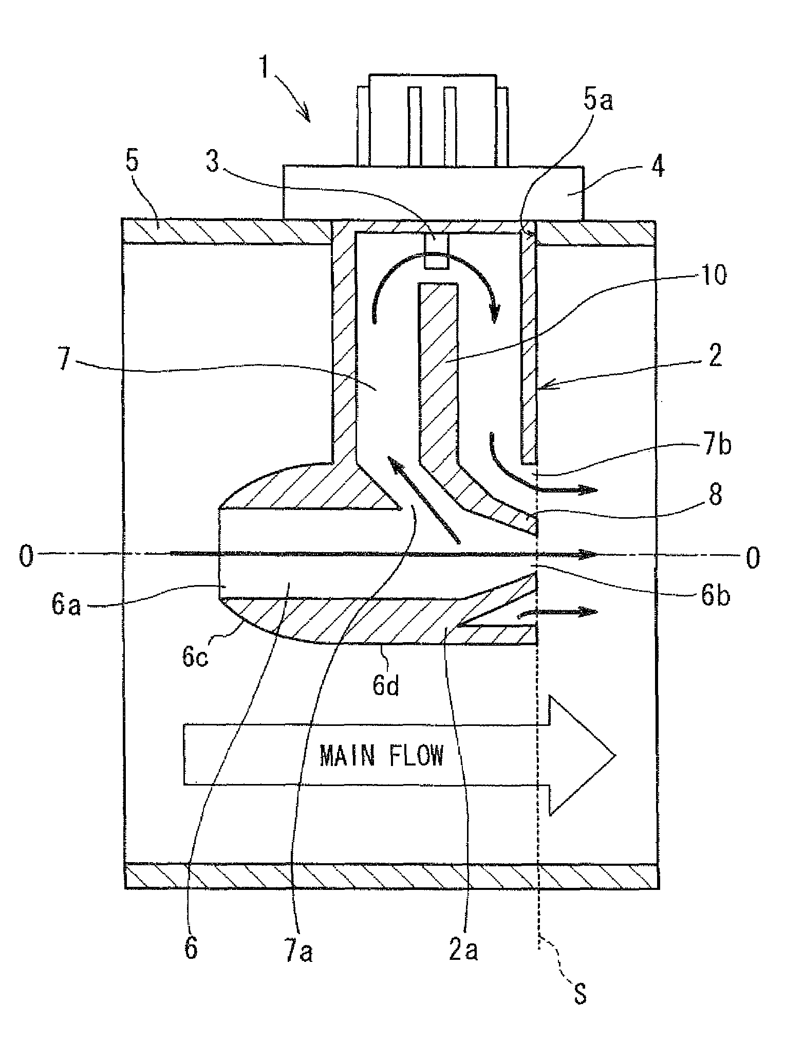
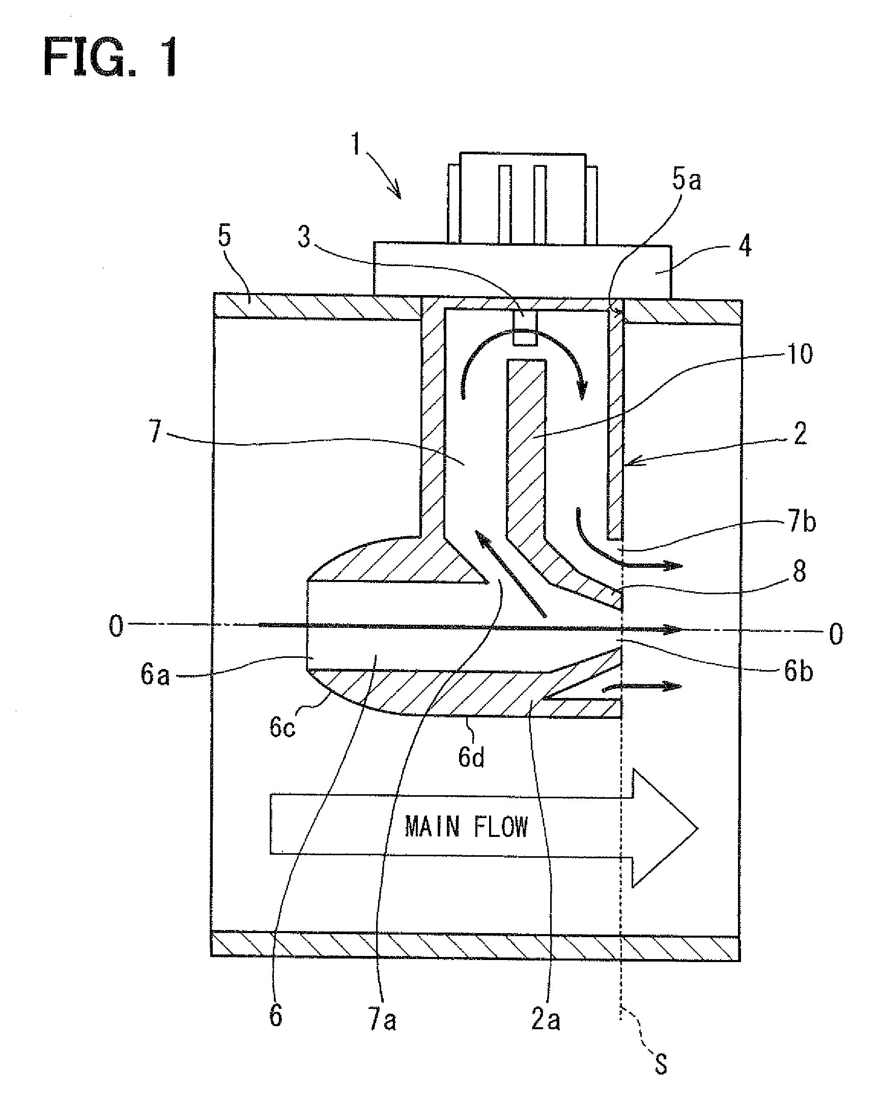
[0043]FIGS. 6A to 6C show examples of an air flow measuring device 1 according to a third embodiment of the present invention. In this embodiment, as shown in FIGS. 6A to 6C, the sub-bypass passage 7 described in the first embodiment is omitted, and only one bypass passage 6 is provided. Thus, in the third embodiment, a flow amount sensor 3 is located in the bypass passage 6 of the tube body 2a to detect a flow amount of air flowing in the bypass passage 6.
[0044]The tube body 2a is configured to define therein the bypass passage 6, as shown in FIGS. 6A to 6C. In the example of FIG. 6A, the first portion 6c of the tube body 2a is configured to have a convex curve surface in which the outer diameter of the tube body 2a is gradually increased by a predetermined ratio, and the second portion 6d positioned downstream from the first portion 6c in the tube body 2a has approximately a cylindrical shape, similarly to the tube body 2a of the above-described first embodiment. In the third embo...
PUM
 Abstract
Description
Claims
Application Information
 - Generate Ideas
- Intellectual Property
- Life Sciences
- Materials
- Tech Scout
- Unparalleled Data Quality
- Higher Quality Content
- 60% Fewer Hallucinations
Browse by: Latest US Patents, China's latest patents, Technical Efficacy Thesaurus, Application Domain, Technology Topic, Popular Technical Reports.
© 2025 PatSnap. All rights reserved.Legal|Privacy policy|Modern Slavery Act Transparency Statement|Sitemap|About US| Contact US: help@patsnap.com


