Advanced phase shift inspection method

a phase shift and inspection method technology, applied in the field of electronic inspection systems, can solve the problems of considerable cost and complexity of prior systems incorporating rotational capability, and achieve the effect of cost and complexity

Inactive Publication Date: 2010-02-16
KLA CORP
View PDF13 Cites 15 Cited by
  • Summary
  • Abstract
  • Description
  • Claims
  • Application Information

AI Technical Summary

Benefits of technology

[0023]The present system also has the ability to simultaneously detect defects with both transmitted and reflected light. This capability is significant because the additional information can be helpful in determining the nature of the defect and thereby permits the automatic classification of defects.
[0029]Subsequent to the initial calibration procedure, the system scans the desired specimen to inspect it for defects. The system remaps the TR readings into single greyscale values thereby permitting a combination of transmitted and reflected images into a single intensity profile. The system may include filters networks to improve detectability.
[0032]The system further includes a transmitted and reflected light algorithm or method for improving detection of particular types of features expected to be encountered on the mask. The algorithm provides the system with the ability to differentiate and resolve anomalies found on strong phase shift type masks, including alternating and darkfield alternating phase shift mask types. Further, the algorithm provides the ability to manage image artifacts such as bright chrome halos. The algorithm determines the remap function S=S(T,R), utilizing different species employing different analytical approaches to derive the remap. The species are each designed for a specific anticipated application, and thus the algorithm operates as an expert system to locate anticipated anomalies.

Problems solved by technology

Prior systems incorporated rotational capability at a considerable cost and complexity.

Method used


Image

  • Advanced phase shift inspection method
  • Advanced phase shift inspection method
  • Advanced phase shift inspection method

Examples


Embodiment Construction

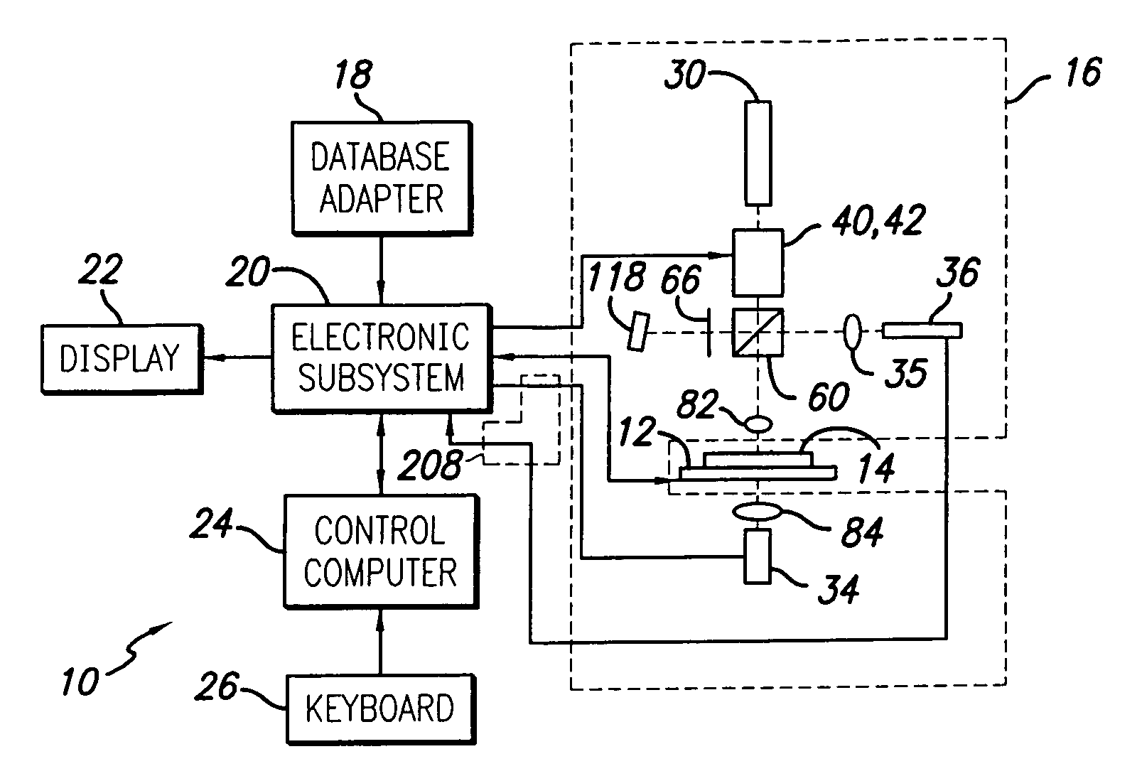
[0072]Referring now to the drawings, a block diagram of an automatic optical inspection system in accordance with the first aspect of the system is shown at 10. The system is capable of inspecting substrates, such as reticles, photomasks, semiconductor wafers, phase shift masks, and Embedded Phase Shift Masks (EPSMs).

[0073]The system can perform several types of inspection: transmitted light inspection, reflected light inspection, simultaneous reflected and transmitted inspection, and phase shift measurement. In transmitted light inspection, light impinges on the substrate, a photomask for example, and the amount of light transmitted through the mask is detected. In reflected light inspection, the light reflecting from a surface of the substrate under test is measured. During phase shift inspection, the amount of phase shift between two reflected coherent light beams is detected at each point on the mask while transmitted light inspection takes place concurrently. The phase shift is...


PUM

PropertyMeasurementUnit
thicknessaaaaaaaaaa
radiusaaaaaaaaaa
reflectanceaaaaaaaaaa

Abstract

A method and apparatus for inspecting patterned transmissive substrates, such as photomasks, for unwanted particles and features occurring on the transmissive as well as pattern defects. A transmissive substrate is illuminated by a laser through an optical system comprised of a laser scanning system, individual transmitted and reflected light collection optics and detectors collect and generate signals representative of the light transmitted and reflected by the substrate. The defect identification of the substrate is performed using only those transmitted and reflected light signals, and other signals derived from them, such as greyscale representations and image features. Defect identification is performed using a pattern inspection algorithm by comparing image feature representations of the present substrate with an idealized representation thereof, and using an advanced phase shift algorithm that accounts for particular types of expected anomalies.

Description

[0001]This application is a continuation of U.S. patent application Ser. No. 09 / 991,327, (now U.S. Pat. No. 6,863,560) entitled “Advanced phase Shift Inspection Method,” filed on Nov. 9, 2001, which is based on U.S. Provisional Patent Application 60 / 248,149, entitled “Advanced Phase Shift Inspection Method,” filed on Nov. 13, 2000.BACKGROUND OF THE INVENTION[0002]1. Field of the Invention[0003]The present invention relates generally to electro-optical inspection systems, and more particularly to a method or algorithm for automated photomask inspection to detect defects on optical masks, reticles, and the like.[0004]2. Description of the Related Art[0005]Integrated circuits are made by photolithographic processes which use photomasks or reticles and an associated light source to project a circuit image onto a silicon wafer. A high production yield is contingent on having defect free masks and reticles. Since it is inevitable that defects will occur in the mask, these defects have to ...

Claims


Application Information

Patent Timeline
Patent Type & Authority Patents(United States)
IPC IPC(8): G06K9/00G01N21/00G01N21/956G03F1/00
CPCG01N21/95607G03F1/26G03F1/72G03F1/84
Inventor EMERY, DAVID G.
Owner KLA CORP
Why Eureka
Try Eureka