
Voice coil type lens drive assembly

a voice coil and lens drive technology, applied in the direction of dynamo-electric components, dynamo-electric machines, instruments, etc., can solve the problems of poor efficiency of the lens drive assembly, difficult to apply the above construction to a downsized lens drive assembly, etc., to achieve convenient handling, improve the accuracy of winding height, and facilitate stabilization

Inactive Publication Date: 2010-02-16
CHUNG HUANG TIEN
View PDF4 Cites 33 Cited by
  • Summary
  • Abstract
  • Description
  • Claims
  • Application Information

AI Technical Summary

Benefits of technology

"The present invention provides a voice coil type lens drive assembly for adjusting the focus of a lens by utilizing a repulsive magnetic force created upon energization of coil of a movable unit loaded with the lens. The assembly includes a base, an electrically conductive spring, a metallic yoke, magnets, a movable unit, a leaf spring, and an upper cover frame. The movable unit comprises a coil base and coils, the coil base having projections on its outer four faces and the coils being wound round the projections. The assembly allows for easy stabilization of the coil winding height, efficient utilization of the magnetic repulsive force, and effective adjustment of the lens focus. The construction is applicable to a downsized lens drive assembly and is convenient to handle."

Problems solved by technology

As a result, the gap between the coil 123d and the magnet M becomes wider and hence the magnetic repulsive force induced upon energization cannot be utilized effectively, thus affording a lens drive assembly of poor efficiency.
At the same time, an outline of the entire assembly becomes large and thus it becomes difficult to apply the above construction to a downsized lens drive assembly.
Besides, there is a fear of wire breaking in a connection between plural coils 123d.
This is unstable in point of handling.

Method used


Image

  • Voice coil type lens drive assembly
  • Voice coil type lens drive assembly
  • Voice coil type lens drive assembly

Examples


Embodiment Construction

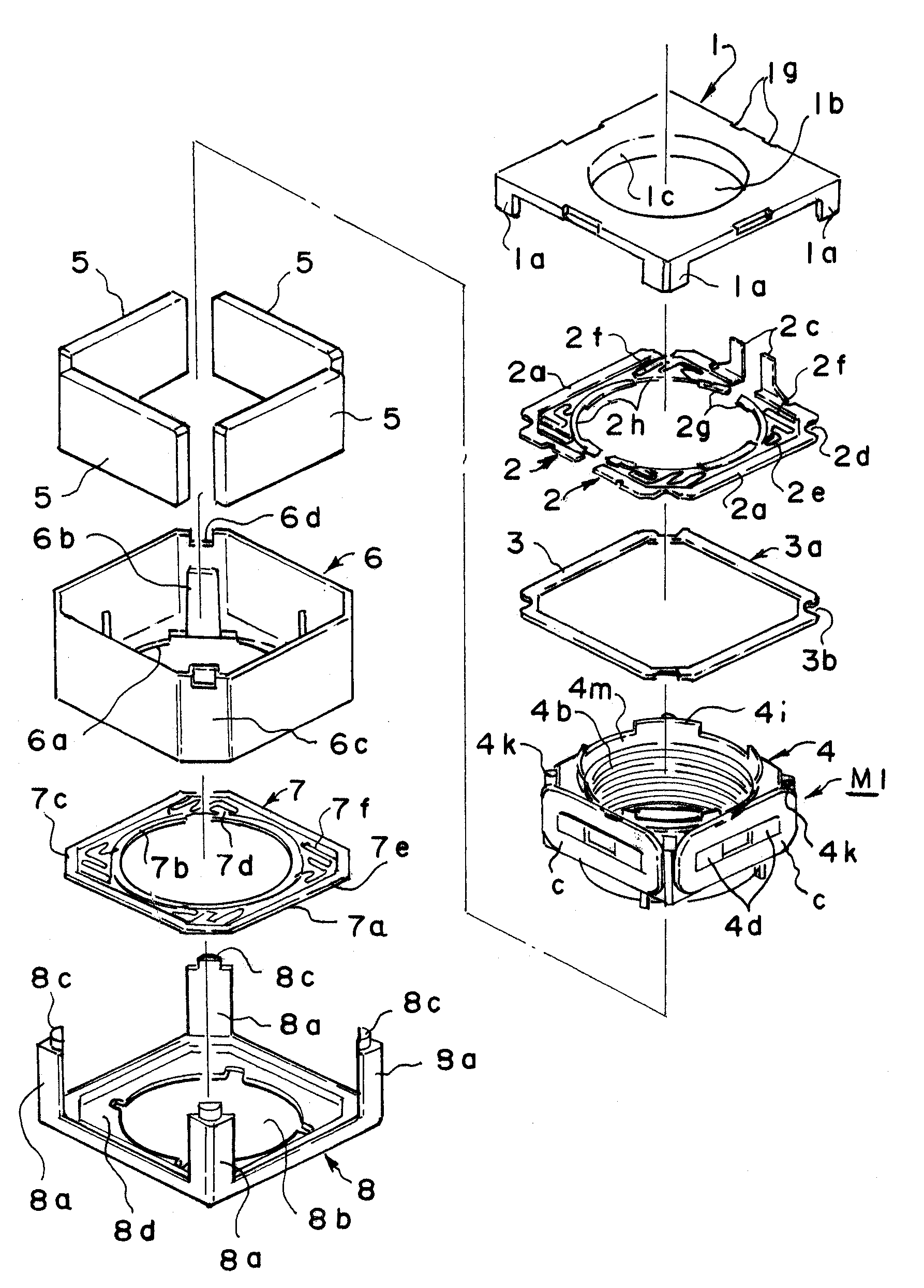
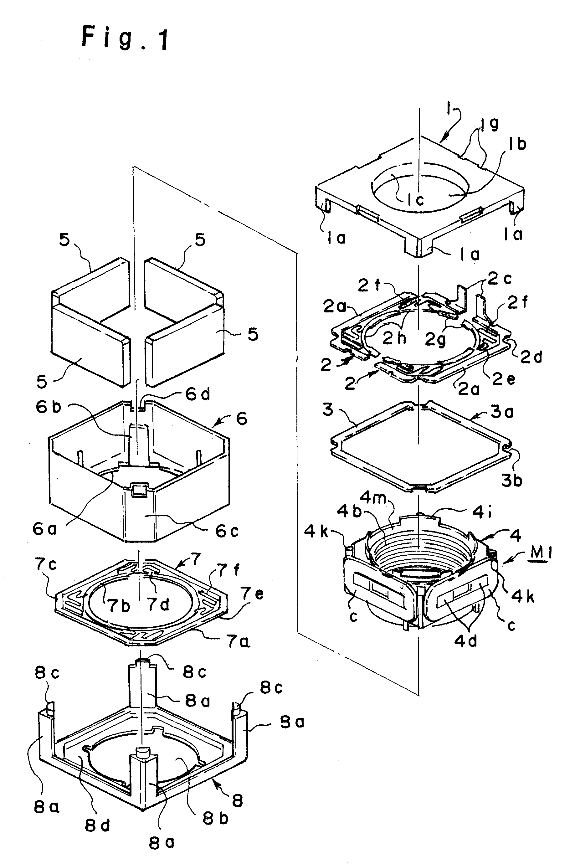
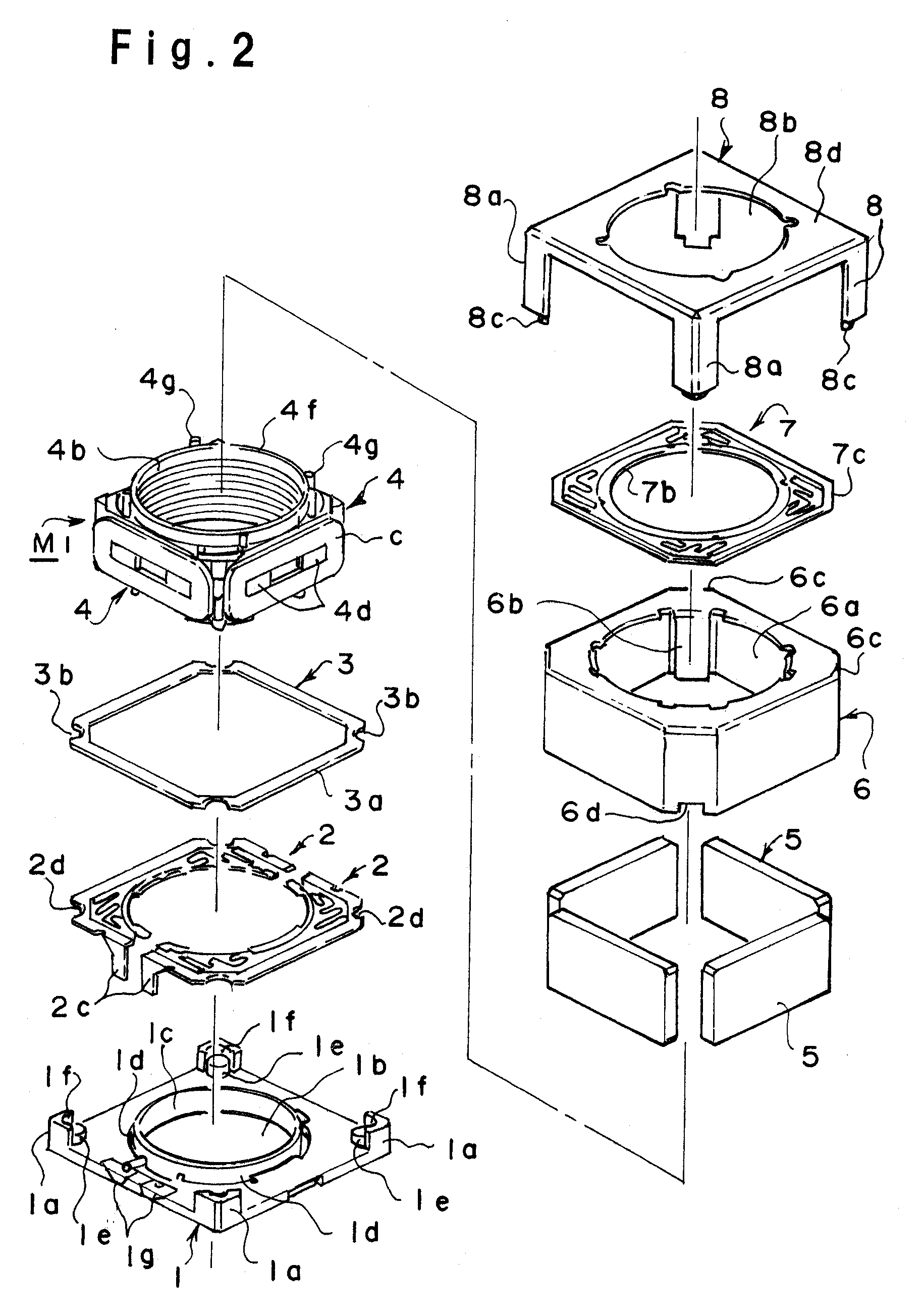
[0025]An embodiment of the present invention will now be described in detail with reference to the drawings. As shown in FIG. 1, a voice coil type lens drive assembly using a motor embodying the present invention is constituted by stacking within a cover frame 8 a leaf spring 7, a yoke 6, magnets 5, a coil base 4, a washer 3, electrically conductive springs 2 and a base 1 in this order. In the exploded perspective view for assembly of FIG. 1, as is seen from FIG. 2, the cover frame 8 to be positioned on an upper side is placed below and the components which should underlie the cover frame 8 are assembled successively upwards.

[0026]As shown in FIG. 2, the base 1 includes a body which is formed by molding in a quadrangular plate shape with use of a synthetic resin, and four support rods 1a projecting upwards are formed on the four corners of the body. A lens aperture 1b is formed centrally of the body and a cylindrical guide 1c is erected along a peripheral edge of the lens aperture.

[...


PUM


Abstract

By maintaining a relative position of coils of a movable unit with respect to fixed magnets in a normal state to stabilize a relative position of the movable unit with respect to the whole of a lens drive assembly, the lens drive assembly is provided as an assembly capable of adjusting the focus of a lens in a satisfactory manner. In a voice coil type lens drive assembly for adjusting the focus of a lens, a spring 6, a yoke 6 with magnets 5 and a movable unit M1 attached thereto, and electrically conductive springs 2, are accommodated in this order on a base 1 and a connecting portion of a cover frame 8 and that of the base 1 are connected together to unite the two components. At the same time, cut-in portions 6d formed in end portions of the yoke 6, which is a metallic yoke, are fitted on projections 1e of the base 1 and both are joined together with connections to the cover frame 8 as guide.

Description

BACKGROUND OF THE INVENTION[0001]1. Field of the Invention[0002]The present invention relates to a voice coil type lens drive assembly for adjusting the focus of a lens by utilizing a repulsive magnetic force which a magnetic field created upon energization of a coil induces between the coil and a fixed magnet opposed to the coil.[0003]2. Description of the Related Art[0004]Heretofore, in connection with a voice coil type lens drive assembly for adjusting the focus of a lens by utilizing a repulsive magnetic force which a magnetic field created upon energization of a coil induces between the coil and a fixed magnet opposed to the coil, a method for winding the coil around a movable unit has been known as is disclosed, for example, in Patent Literature 1 (Japanese Registered Utility Model No. 3127325, see FIG. 7). According to this conventional method, as shown in FIG. 15, a coil 123d having been wound beforehand in a predetermined shape is mounted suitably around a coil base 243.[00...

Claims


Application Information

Patent Timeline
Patent Type & Authority Patents(United States)
IPC IPC(8): G02B7/02
CPCG02B7/08H02K33/18H02K41/0356
Inventor CHUNG, HUANG TIEN
Owner CHUNG HUANG TIEN
Learn More