
Operation at mobile terminal when communicating with remote camera

a mobile terminal and camera technology, applied in the field of remote camera control, can solve the problem of not being able to acquire a moving picture and control a camera, and achieve the effect of improving operability at the mobile terminal

Inactive Publication Date: 2010-02-16
CANON KK
View PDF36 Cites 24 Cited by
  • Summary
  • Abstract
  • Description
  • Claims
  • Application Information

AI Technical Summary

Benefits of technology

The present invention aims to enhance the operability of a mobile terminal for performing camera control and video acquisition from a camera server. This is achieved by providing a storage medium with program code means for assigning operations for video acquisition and camera control to the mobile terminal's operating units and executing processing accordingly. The mobile terminal is also capable of communicating with the camera server via a network and displaying the camera server's video on its display unit. The invention also includes a control unit that can obtain video from the camera server and display it on the mobile terminal's display unit with a frame indicative of the area to be obtained from the camera. The mobile terminal can also include a vibrator notifying unit and a display control unit that can display the video in different colors during control. Overall, the invention improves the user experience and ease of use for mobile terminals in controlling the camera and acquiring video from the camera server.

Problems solved by technology

A problem relating to camera control arises between the camera server and operating terminals when camera control operations such as pan, tilt and zoom are allowed from a plurality of operating terminals simultaneously.
It is not possible to acquire a moving picture and control a camera by an operation similar to that of a personal computer or the like using an existing mobile terminal having a small display screen and only a limited number of operating keys.

Method used


Image

  • Operation at mobile terminal when communicating with remote camera
  • Operation at mobile terminal when communicating with remote camera
  • Operation at mobile terminal when communicating with remote camera

Examples


Embodiment Construction

[0040]A preferred embodiment of the present invention will be described in detail in accordance with the accompanying drawings. However, the dimensions, shapes and relative positions of the constituent parts shown in the embodiment should be changed as convenient depending on various conditions and on the structure of the apparatus adapted to the invention, and the invention is not limited to the embodiments described herein.

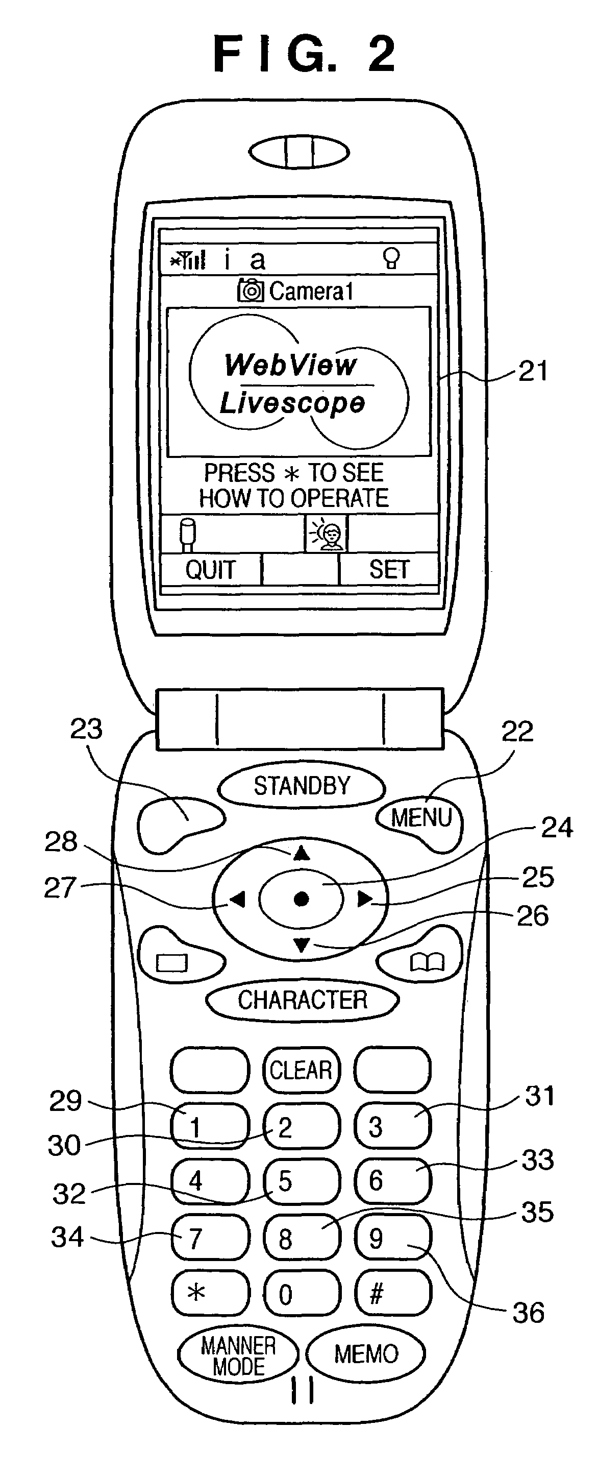
[0041]In this embodiment of the present invention, a viewer program for displaying video from a camera and for controlling a camera is downloaded and installed to a mobile telephone, the mobile telephone accesses a camera server using the viewer program and controls the camera while video is being viewed.

[0042]FIG. 1 is a diagram illustrating the configuration of a system according to an embodiment of the present invention.

[0043]As shown in FIG. 1, a camera server 11 and a display terminal 12 are logically connected through a network 13. A mobile telephone is as...


PUM


Abstract

A mobile terminal, which is capable of communicating with a camera server via a network, has a display unit and a plurality of operating units. Operations for acquiring video and for controlling a camera are assigned to respective ones of the plurality of operating units. Depending upon the operation of the plurality of operating units, processing is executed for acquiring video from the camera server or for instructing the camera server to control the camera.

Description

FIELD OF THE INVENTION[0001]This invention relates to a technique for controlling a remote camera while video from the remote camera is viewed using a mobile terminal such as a mobile telephone.BACKGROUND OF THE INVENTION[0002]A system available in the art enables video from a camera disposed at a remote location to be observed by a number of people at a number of locations via a network. For example, there is a system in which a computer-controllable camera is connected to a personal computer that has been connected to the Internet, and not only is real-time video captured by the camera distributed to accessing individuals but these individuals are also allowed to control the camera through a WWW (World-Wide Web) server on the Internet (e.g., see the specification of Japanese Patent Application Laid-Open No. 10-040185). The side that distributes the video and the side that observes it are in a server-client relationship. In the description that follows, the apparatus or system on t...

Claims


Application Information

Patent Timeline
Patent Type & Authority Patents(United States)
IPC IPC(8): H04N5/232H04L12/16H04B1/40H04N7/18
CPCH04N5/232H04N5/23206H04N7/181H04N23/661H04N23/631H04N23/635H04N23/695H04Q9/00H04B1/40
Inventor KAWAI, TOMOAKIOHNISHI, MOTOO
Owner CANON KK
Learn More