
Airbag apparatus

a technology of airbags and airbags, applied in the direction of superstructure subunits, vehicle components, pedestrian/occupant safety arrangements, etc., can solve the problems of simple rubber strip, easy change of plastic, no member, etc., and achieve smooth expansion of airbags and favorable appearance and stability.

Inactive Publication Date: 2010-02-02
NIHON PLAST CO LTD
View PDF7 Cites 12 Cited by
  • Summary
  • Abstract
  • Description
  • Claims
  • Application Information

AI Technical Summary

Benefits of technology

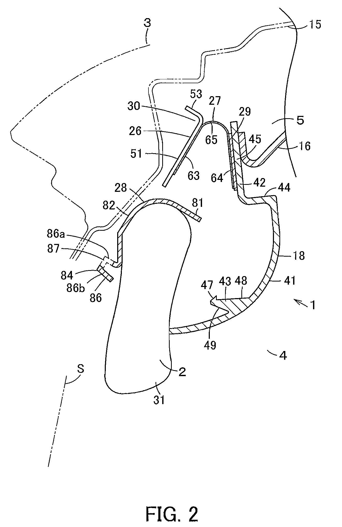
[0009]Then, according to the above constitution, during normal times when the airbag is folded into a long-thin shape, before or after the airbag apparatus is fitted to the to-be-fitted member, the fitting part disposed on one end of the main part along the longitudinal direction is supported by the supporting body and the engaging part disposed on the other side of the main part along the longitudinal direction is engaged with the engagement receiving part of the supporting body, by which the airbag is covered with the cover body so as to be favorable in appearance and stable. On expansion of the airbag, the airbag presses the cover body, thereby the engaging part is disengaged from the engagement receiving part, allowing for movement of the cover body, and allowing a smooth expansion of the airbag. Since the engagement receiving part is disposed on the supporting body, the airbag apparatus is available as a module, and the cover body is supported even before the airbag apparatus is fitted to the to-be-fitted member.
[0011]Then, in the above constitution, the airbag is protected by the guide part of a protector during normal times when the airbag is folded into a long-thin shape and also on expansion. Since the engagement receiving part is disposed on the protector, the airbag apparatus is made simplified in constitution, thereby reducing the production cost.
[0013]Then, in the above constitution, since the airbag receiving part is equipped, the engaging part reliably receives a force by which the airbag is inflated and expanded, and the engaging part can be smoothly and quickly disengaged from the engagement receiving part on inflation and expansion of the airbag.
[0016]As described above, according to the airbag apparatus of the present invention, during normal times when the airbag is folded into a long-thin shape, before or after the airbag apparatus is fitted to the to-be-fitted member, a fitting part disposed on one side along the longitudinal direction of the main part is supported by the supporting body and an engaging part disposed on the other side of the main part along the longitudinal direction is engaged with the engagement receiving part of the supporting body, by which the airbag can be covered with the cover body so as to be favorable in appearance and stable. On expansion of an airbag, the airbag presses the cover body, thereby the engaging part is disengaged from the engagement receiving part, allowing for movement of the cover body, and allowing for a smooth expansion of the airbag. Since the engagement receiving part is disposed on the supporting body, the airbag apparatus is available as a module, and the cover body can be supported even before the airbag apparatus is fitted to the to-be-fitted member.

Problems solved by technology

However, in a constitution in which the plastic-made pillar garnish or an interior trim material is elastically deformed, there is a problem that the plastic is softened to easily change the characteristics at an extremely high-temperature, for example, and a trim part of a door weather strip which is simply formed of rubber is difficult in supporting stably a long pillar garnish covering an airbag folded into a long-thin shape.
There is also a problem that before the airbag apparatus is fitted to an automobile, no member is provided for supporting the external edge of the pillar garnish and the pillar garnish may be deformed during transport of the airbag apparatus.

Method used


Image

  • Airbag apparatus
  • Airbag apparatus
  • Airbag apparatus

Examples


Embodiment Construction

[0022]Hereinafter, a description will be given of an embodiment of the airbag apparatus of the present invention with reference to the drawings.

[0023]In FIG. 1 or FIG. 3, reference numeral 1 denotes an airbag apparatus. The airbag apparatus 1 is equipped with an airbag 2 which is called a curtain airbag or an airbag for side collision. As shown in FIG. 1, during normal times, the airbag apparatus 1 is disposed at a roof side part 5 as a storage position of a cabin 4 in a body 3 of an automobile which is a vehicle. As shown in FIG. 2, on receiving an impact resulting from a side collision, rolling over or the like, it expands to the side of a passenger in a planar configuration, thereby protecting a passenger to be protected. It is noted that the following explanation will be made on the basis of an understanding that directions including vertical and front-back directions are based on a direction in which a vehicle advances straight, and for internal and external sides, for example,...


PUM


Abstract

An airbag apparatus equipped with an airbag, a garnish, a hinge, a protector and a bracket fixed to a vehicle body. An upper side of the garnish is supported by the bracket via the hinge. An engaging part protruding from the lower part of a garnish main part is engaged with an engagement receiving part disposed at the protector. Normally, the engaging part is engaged with the engagement receiving part, thereby retaining the shape of the garnish. On expansion of the airbag, the airbag presses the engaging part, by which the engaging part is disengaged from the engagement receiving part, and the garnish is opened smoothly. The airbag can be covered with the garnish, thereby allowing the garnish to move smoothly on expansion of the airbag.

Description

INCORPORATION BY REFERENCE[0001]The present invention claims priority under 35 U.S.C. §119 to Japanese Patent Application No. 2007-249831 filed on Sep. 26, 2007. The content of the application is incorporated herein by reference in its entirety.FIELD OF THE INVENTION[0002]The present invention relates to an airbag apparatus which expands an airbag, for example, along window parts on the side of a cabin of a vehicle.BACKGROUND OF THE INVENTION[0003]Conventionally, regarding an airbag apparatus equipped with an airbag which is inflated and expanded upon injection of gas, known is a so-called curtain airbag apparatus which expands along window parts of the door on the side of a cabin of an automobile. An airbag used in this airbag apparatus is normally folded into a long-thin shape and disposed along the upper edge of the window part on the side of the cabin. Then, upon impact such as a side collision or rolling over, gas is supplied from an inflator, by which the airbag is expanded an...

Claims


Application Information

Patent Timeline
Patent Type & Authority Patents(United States)
IPC IPC(8): B60R21/16B60R21/20B60R13/02B60R21/213B60R21/215
CPCB60R21/213B60R2021/161
Inventor HIDAKA, NOBUYUKIFUKUDA, TAKERUINAZU, TADASHIHONDA, TAKASHINAKAMURA, TATSUHIKOKAMIO, KENICHI
Owner NIHON PLAST CO LTD
Learn More