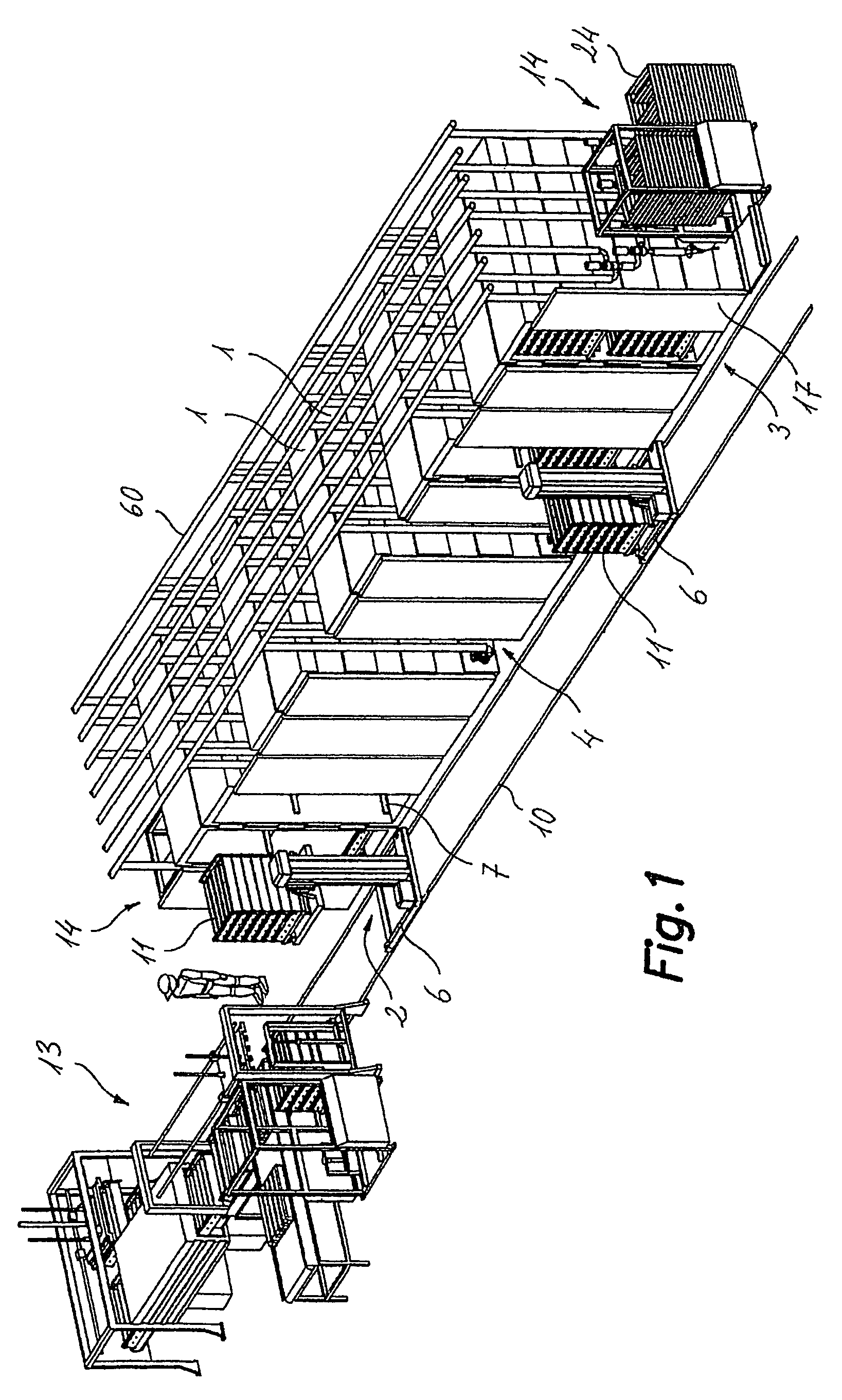
[0009]In accordance with this invention, the previous objective is obtained by providing a food cooking installation, of the type comprising numerous cooking tanks to receive the food items to be cooked; the means of loading / unloading the food items into / from the said cooking tanks; the means of heating the liquid associated with a heated liquid tank; the means of cooling the liquid associated with a cooled liquid tank and a connection to the mains water supply; with the means of conveying, driving and storing the liquids, which are connected to a heated liquid container, a cooled liquid container and a piped mains water delivery point with the previously described cooking tanks so that the said cooking tanks can be independently filled and emptied, with the said liquids being optionally returned to their respective tanks, and the contained food items can be subjected to successive baths for different periods of time and at different temperatures, with at least one of the said baths being a cooking bath and another for cooling, with the installation characterised because each of the said cooking tanks comprising at least one side opening with the means for being hermetically sealed, through which the food items can be loaded / unloaded by the said means of loading.
[0011]The fact that there is at least one side opening for the loading / unloading of each cooking tank allows the use of the means of loading that operate from ground level, eliminating the need for a high ceiling height and preventing the risks involved in overhead transport of the loads using cranes. Thus, the said means of loading comprises at least one transport / lifting trolley fitted with the handling means capable of holding, lifting and lowering a food item batch and of transferring the said food item batch inside one of the cooking tanks or to remove it through the said opening. This transport / lifting trolley, of which there is at least one, will move along a path and, according to a basic construction example, the said cooking tanks are arranged to form a row along one side of the said path, with their openings aligned in a plane parallel to the same, although other layouts are also possible. The cooking tanks are installed in groups of two, one next to the other at the sides, leaving a separation space between two groups of two cooking tanks that is sufficient to permit at least one complete opening movement of one of the cooking tanks adjacent to one of the said separation spaces. Some of the said means of conveying, driving and storing liquids are arranged on one free side wall of each cooking tank which, in the intermediate tanks is adjacent to the said separation space, and associated with inlet / outlet pipes for liquids to and from the cooking tank through the said free side wall.
[0012]Preferably, the trolley is self-propelled and moves over rails along the said path and able to make selective stops in front of any of the cooking tanks that is selected for introducing or removing a batch of food items under the control of programmable electronic means. The said means of handling associated with the trolley comprises a horizontal support element connected to a vertical lift device, together with transversal guides mounted on the said horizontal support element, with the said lift device being able to place the said horizontal support element at various suitable heights so that the said transversal guides can be aligned with some corresponding guides installed on one or more levels inside the cooking tank. For complete automation of the loading / unloading operations, the said transversal guides for the means of handling the trolley are associated with the means of drive that cooperate with the means of drive associated with the said cooking tank guides for introducing or removing a batch of food items into / from the same. The cited means of drive for the lower cooking tank guides are driven by motors located outside on the said free side wall of each cooking tank. These motors are coupled to the means of drive through the said free side walls by means of adequately sealed transmissions.
[0014]In order to optimise energy costs, each cooking tank includes at least one steam inlet connected to a steam supply via a valve. The steam is distributed inside the cooking tank by means of perforated piping to mix the said steam, whether it is a heated liquid from the said heated liquid tank or mains supply water from the mains supply water connection, or a mixture of the two, inside the cooking tank. In this way, the liquid's temperature is raised to the required level under the control of programmable electronic means. For example, a pre-cooking bath may be carried out by filling the cooking tank with mains supply water at environmental temperature and raising its temperature inside the cooking tank by bubbling steam through it until an adequate level is achieved of, for example, 50-60° C., or a cooking bath by filling the cooking tank with liquid, generally water, that has been previously heated by the means of heating to approximately 40-50° C. and then raising its temperature inside the cooking tank be bubbling steam through it until an adequate level is achieved for the desired heat treatment, for example, approximately 70-80° C. A liquid recirculation system has been planned, driven by a pump, between a tank's inlet and outlet in order to achieve temperature uniformity inside the tank and thus prevent any possible temperature differences through the various areas inside the tank.
[0015]With this arrangement, the food item cooking installation of this invention benefits from the advantages of the immersion cooking system, such as ease of obtaining uniform temperature inside the tank, with the advantages of the steam action system, such as loading through side openings and significant economic savings.