
Developing apparatus featuring multiple magnetic rollers for developing a latent image multiple times

a technology of developing apparatus and latent image, applied in the field of developing apparatus, can solve the problems of affecting the toner image, bringing the retained developer into contact with the photosensitive drum, and generating a blank area image, so as to prevent the image from being defectiv

Inactive Publication Date: 2010-01-26
CANON KK
View PDF10 Cites 12 Cited by
  • Summary
  • Abstract
  • Description
  • Claims
  • Application Information

AI Technical Summary

Benefits of technology

[0027]Therefore, an object of the present invention is to provide a developing apparatus capable of preventing an image defect due to a retention of a developer which is caused by delivering the developer carried by the first developer carrying member to the second developer carrying member.

Problems solved by technology

However, in the developing apparatus 1A, there is a possibility to be generated a blank area image which is one of image defects caused by an edge enhancement.
However, there arises the following problem in the structure of the developing apparatus 1B adopting the twin-sleeve developing method.
When the retained developer is excessively increased, there is a possibility that the retained developer is brought into contact with the photosensitive drum and disturbs the toner image formed on the photosensitive drum.
As a result, a partial defect (i.e., unevenness) of the toner is caused, thereby forming an image making an extremely bad impression after the usage of the developing apparatus for a long period of time.
This is a problem of a so-called “bridge phenomenon of a developer”.
As described above, even when the magnetic field for promoting the delivery of the developer is formed to prevent the retention of the developer in a developer delivering part of two sleeves, in a case where the “bridge phenomenon of the developer” is caused in another place, a disturb of the toner image is finally caused.

Method used


Image

  • Developing apparatus featuring multiple magnetic rollers for developing a latent image multiple times
  • Developing apparatus featuring multiple magnetic rollers for developing a latent image multiple times
  • Developing apparatus featuring multiple magnetic rollers for developing a latent image multiple times

Examples


first embodiment

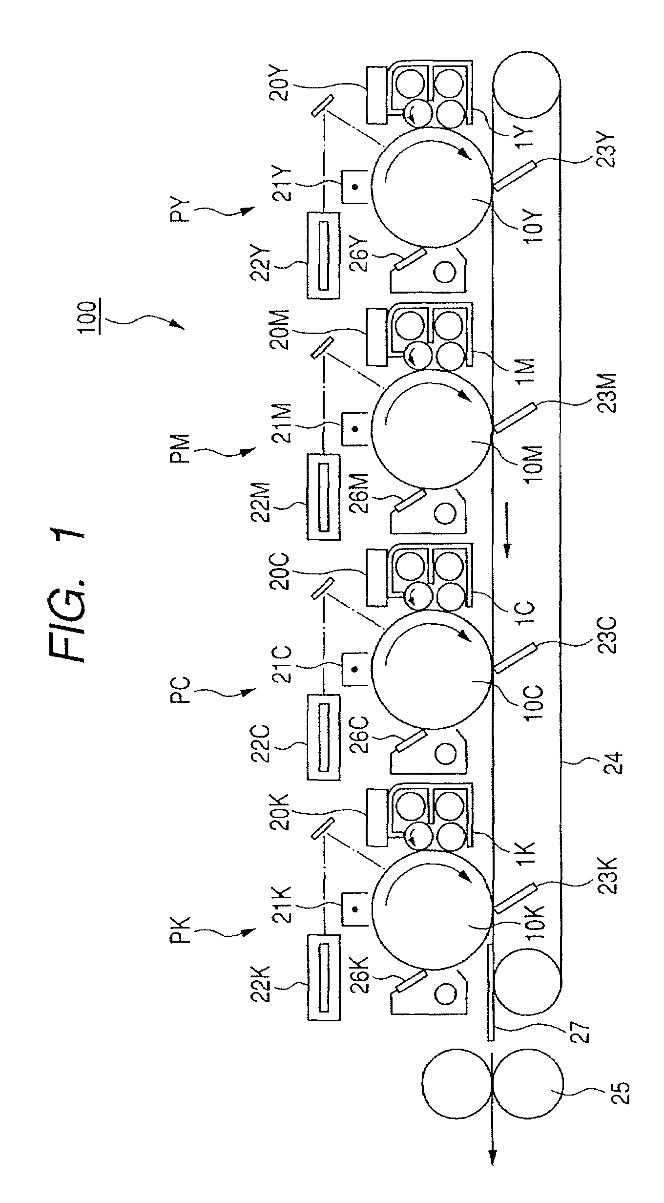
[0041]First, with reference to FIG. 1, a description will be given of a schematic structure of an image forming apparatus according to an embodiment of the present invention, and thereafter a description will be given of a developing apparatus that constitutes a characteristic portion of the present invention. In this embodiment, the image forming apparatus 100 is directed to a multicolor image forming apparatus of a tandem type using an electrophotographic printing method. However, the present invention is not limited to the above-mentioned structure.

[0042]A multicolor image forming apparatus according to this embodiment includes image forming portions for Yellow (Y), Magenta (M), Cyan (C), and Black (B) which are arranged in a line, that is, an image forming stations P (PY, PM. PC, and PK), and a conveyor belt 24 serving as a transfer material carrying member for bearing and carrying a transfer material S.

[0043]Each image forming stations P (PY, PM. PC, and PK) has substantially t...

second embodiment

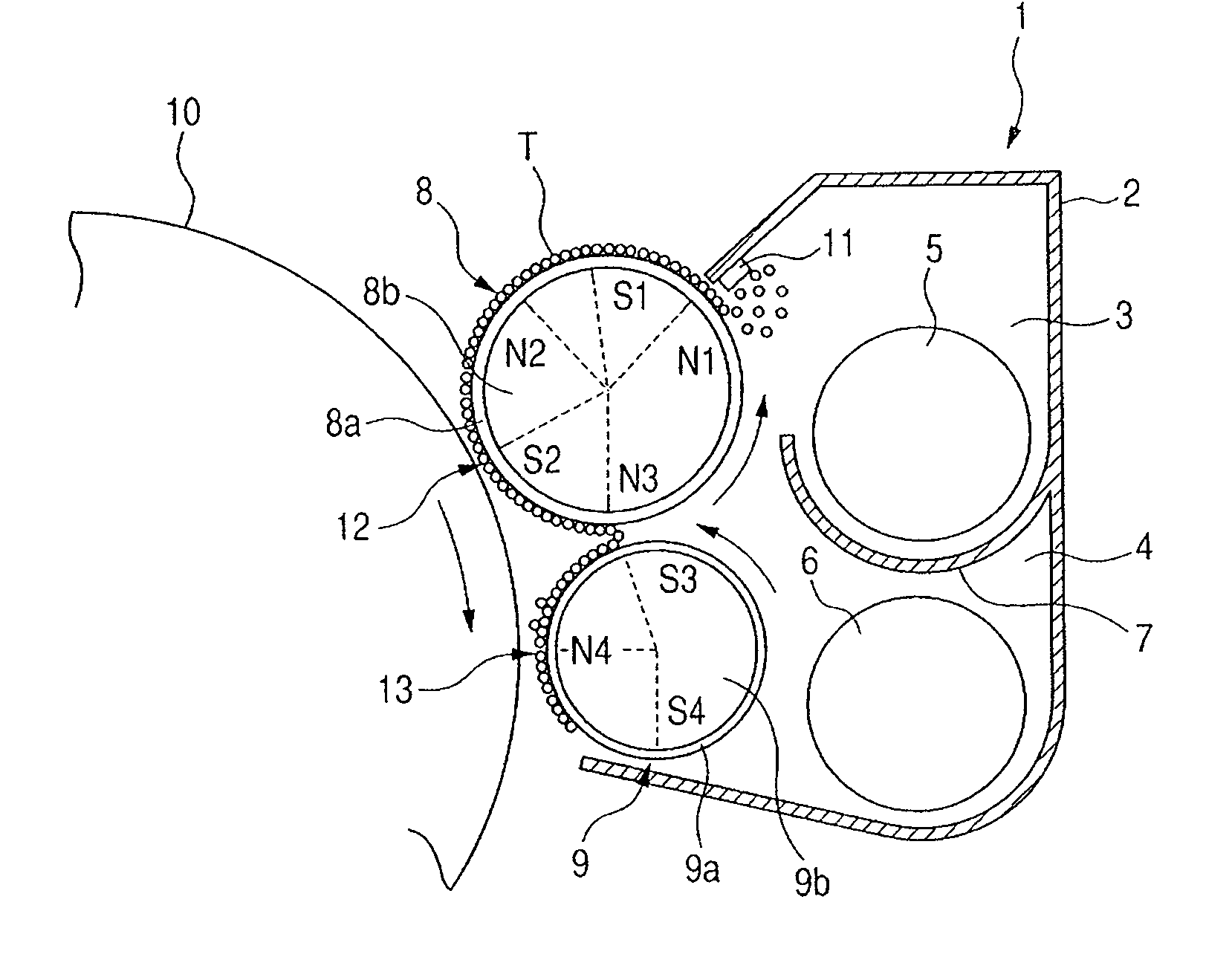
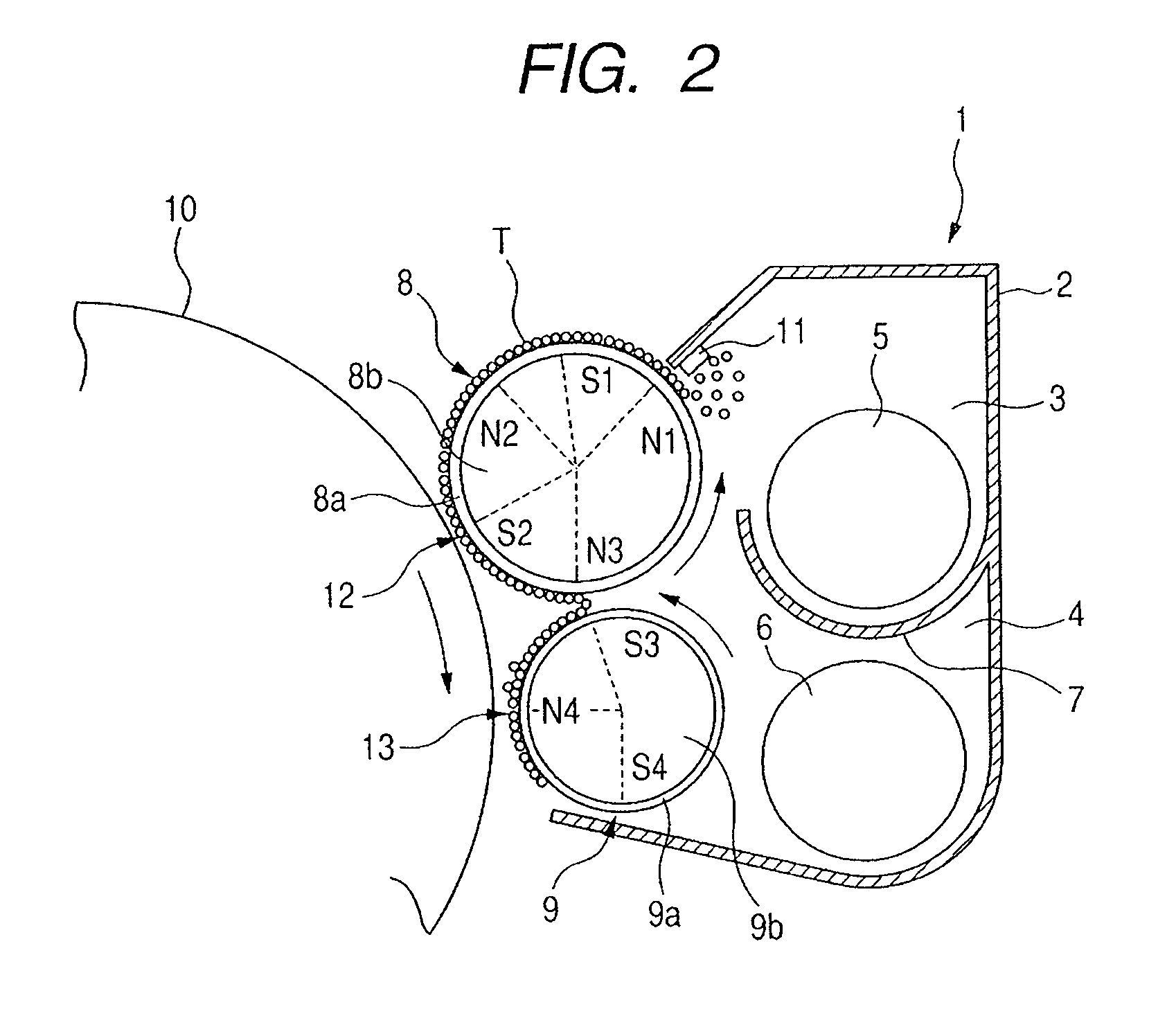
[0099]In the above-mentioned first embodiment, described is the developing apparatus in which the magnetic pole N3 serving as the delivering pole and the magnetic pole S3 of each of the developing sleeves 8a and 9a are substantially opposed to each other.

[0100]On the other hand, for example, as shown in FIG. 5A, when the magnetic pole S2 and the magnetic pole N3 are separated from each other in the developing sleeve 8a, the magnetic force Fr is weakened between the poles, so the developer is attracted by the developing sleeve 9a. Then, as shown in FIG. 5B, magnetic force lines between the magnetic pole S2 and the magnetic pole N3 are blocked off due to the strength and position of the magnetic field of the delivering pole S3 of the developing sleeve 9a, and the magnetic force lines between the magnetic pole S2 and the magnetic pole N4 are generated to thereby cause the bridge phenomenon of the developer.

[0101]Next, in order to increase the magnetic force Fr between the poles and rel...


PUM


Abstract

A developing apparatus in which a first magnet of a first developing sleeve includes a first magnetic pole near a potion opposing to an image bearing member, and a second magnetic pole being downstream of the first magnetic pole; and a second magnet of a second developing sleeve includes a third magnetic pole near a portion opposing to the first sleeve. Assuming that a magnetic force obtained by combining normal direction forces Fr1 and Fr2 of magnetic forces generated by the first and second magnets, respectively, near the first sleeve is Fr, a center direction component of the first sleeve of the force Fr becomes positive between the first magnetic pole and a peak value position of the second magnetic pole, and a center direction component of the force Fr becomes negative between the peak value position and the closest position between both sleeves.

Description

BACKGROUND OF THE INVENTION[0001]1. Field of the Invention[0002]The present invention relates to a developing apparatus for developing an electrostatic image that has been formed through an electrophotographic printing method or an electrostatic recording method on an image bearing member.[0003]2. Description of the Related Art[0004]Up to now, in an image forming apparatus such as a copying machine which adopts an electrophotographic printing method, an electrostatic image formed on an image bearing member such as a photosensitive drum is visualized by adhering a developer onto the electrostatic image. For the developer, a magnetic one-component developer containing magnetic toner, a non-magnetic one-component developer containing non-magnetic toner, two-component developer containing non-magnetic toner and a magnetic carrier, and the like may be appropriately used.[0005]As an example of conventional developing apparatuses using such the developers, a developing apparatus using the ...

Claims


Application Information

Patent Timeline
Patent Type & Authority Patents(United States)
IPC IPC(8): G03G15/09
CPCG03G15/0921G03G2215/0648
Inventor AKASHI, KAZUKIYOSAKAMAKI, TOMOYUKI
Owner CANON KK
Learn More