Lens barrel

a barrel and lens technology, applied in the field of lenses, can solve the problems of plastic lens components being apt to loosen, the lens system encountering deterioration in optical performance, and the deterioration in its own optical performan

Active Publication Date: 2010-01-26
FUJI PHOTO OPTICAL CO LTD
View PDF13 Cites 7 Cited by
  • Summary
  • Abstract
  • Description
  • Claims
  • Application Information

AI Technical Summary

Benefits of technology

[0007]It is therefore an object of the present invention to provide a lens barrel for holding a lens system including at least a plastic lens component which maintains an optical performance of the lens system within tolerable limits even though a spacer ring is used.

Problems solved by technology

If adjacent plastic lens components cause thermal expansion, the lens system encounters deterioration in optical performance due to a change in axial distance between the adjacent plastic lens components.
Further, if firmly forcing the cylindrical spacer ring against a periphery of the plastic lens component, the remaining portion of the plastic lens component causes deformation and, in consequence, optical distortion, which leads to deterioration in its own optical performance.
On the other hand, if loosely forcing the cylindrical spacer ring against a periphery of the plastic lens component, the plastic lens component is apt to become loose.
However, the use of elastic members for respective plastic lens components forming a lens system drives up costs.
In addition, it is disadvantageous in light of a complex internal shape and a tapering bore to form a number of concave parts in a lens holding barrel for receiving plastic lens components therein.
The lens holding barrel thus formed also drive up a manufacturing cost.
In consequence, since it is hard to make the optical performance of the lens system fall within tolerable limits due to changes in two optical factors, i.e. a change in axial distance and a change in air space, the mechanical feature in which a plastic lens component is forced against a cylindrical spacer ring, or vice versa, can not be employed in the conventional lens barrel.

Method used


Image

  • Lens barrel
  • Lens barrel
  • Lens barrel

Examples


Embodiment Construction

[0015]In the following description, parts or mechanisms of a projector which are not direct importance to the invention and parts or mechanisms of a projector which are purely of conventional construction will not be described in detail since their construction and operation can be easily be arrived at by those skilled in the art

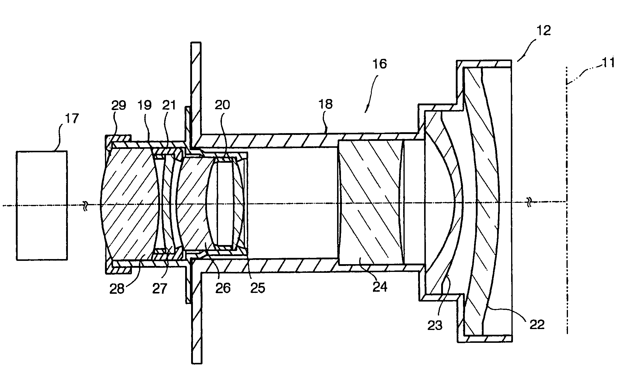
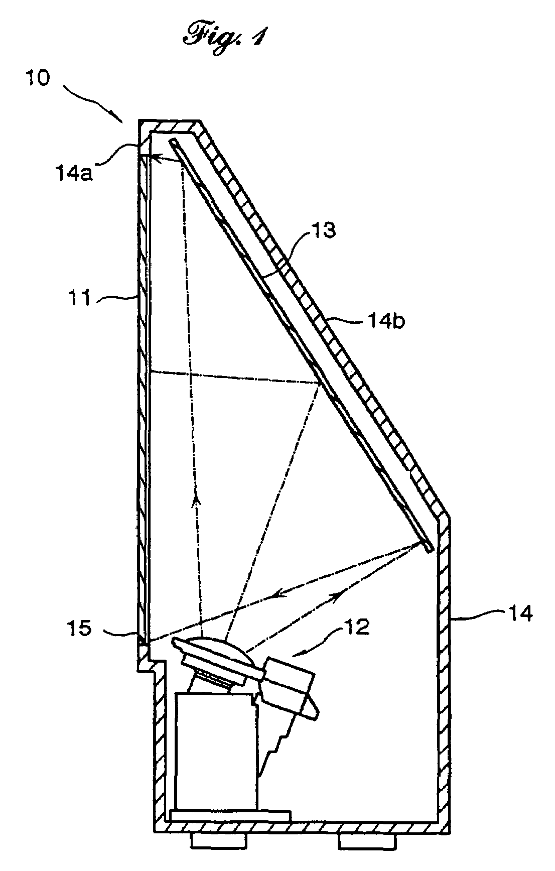
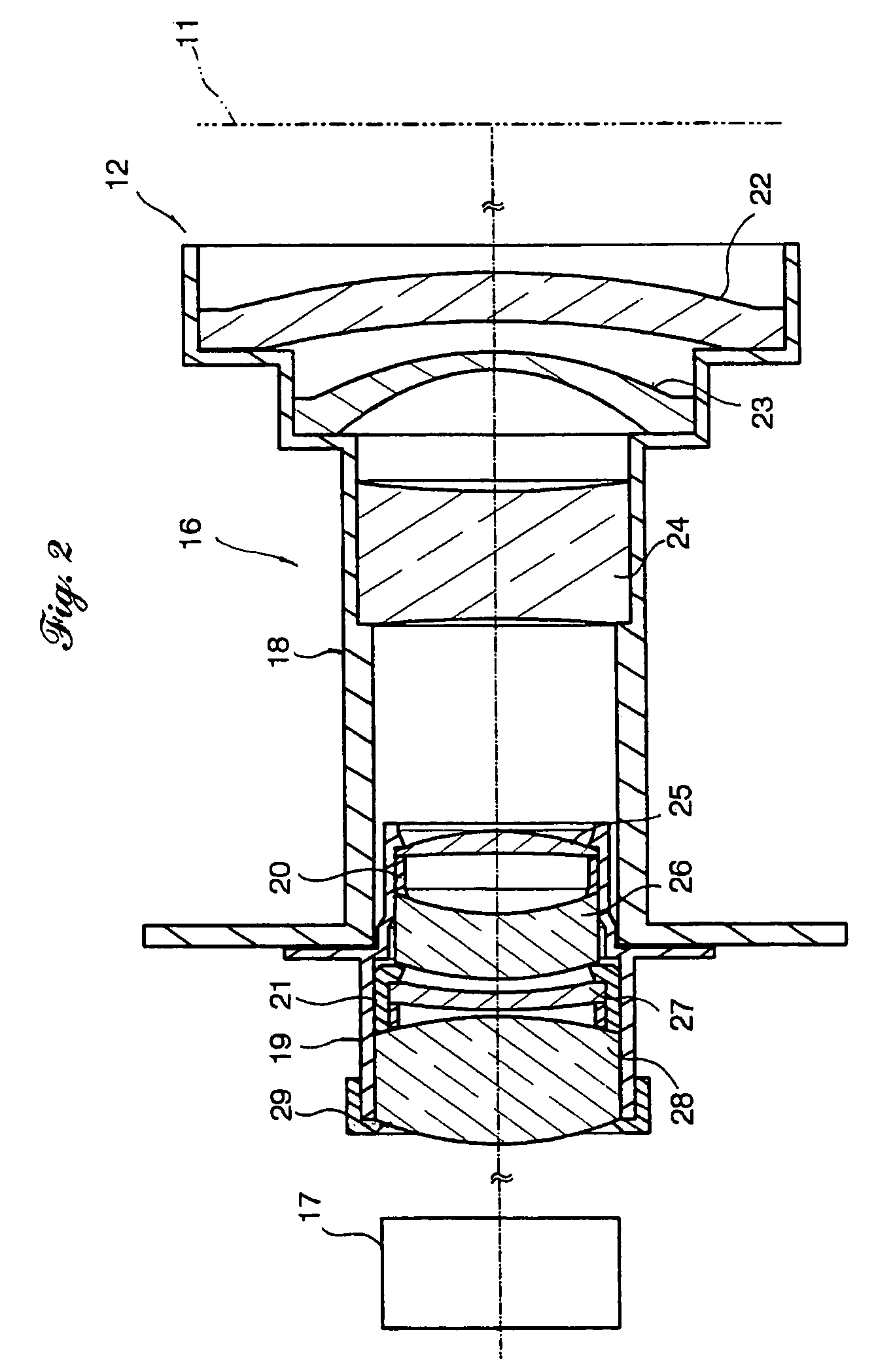
[0016]Referring to the accompanying drawings in detail, and in particular, to FIG. 1 showing a projector 10 of a rear projection type in which a lens barrel according to an embodiment of the present invention is equipped, the projector 10 comprises a projector housing 14 generally shaped in an inverted trapezoid, a projection unit 12 including a projection lens unit, a reflective mirror 13 and a screen 11. Specifically, the projector housing 14 has a front wall 14a in which an opening 15 is formed and a rear wall 14b sloping with respect to the front wall 14a. The screen 11 is fitted in the opening 15. The reflective mirror 13 is mounted to the rear wall 3 w...


PUM


Abstract

A lens barrel for holding a lens system including at least a plastic lens disposed between two glass lenses separated from each other by a spacer ring comprises a cylindrical lens holding barrel fixedly holding the two glass and the plastic lenses, a cylindrical spacer ring fitted in the cylindrical lens holding barrel for elastically supporting the plastic lens therein and positioning the two glass lenses at a predetermined axial distance on opposite sides of the plastic lens.

Description

BACKGROUND OF THE INVENTION[0001]1. Field of the Invention[0002]The present invention relates to a lens barrel for use with a projector, a camera or an endoscope and, more particular, to a lens barrel having a cylindrical spacer ring for regulating an axial distance between two lens components.[0003]2. Description of Related Art[0004]Practically, because of a strong demand for reduction in cost for a lens comprising a lens barrel and a lens system, it is usual to use plastic lens components for the lens system. Such a plastic lens component causes a greater change in dimension than glass lens components due to a change in ambient temperature and a change in ambient humidity. On the other hand, the lens barrel in which a lens system including a plastic lens component or plastic lens components are installed comprises a lens receiving barrel for receiving one or more plastic lens components, a lens holding ring for securely holding the plastic lens component in the lens receiving barr...

Claims


Application Information

Patent Timeline
Patent Type & Authority Patents(United States)
IPC IPC(8): G02B7/02
CPCG02B7/021G02B7/026
Inventor WATANABE, TAKASHI
Owner FUJI PHOTO OPTICAL CO LTD
Why Eureka
Try Eureka