Eureka AIR delivers breakthrough ideas for toughest innovation challenges, trusted by R&D personnel around the world.

Carriage system

a technology of carriage and storage capacity, applied in the field of carriage system, can solve the problems of cumbersome change of station arrangement, cumbersome storage capacity of storage data, and large storage capacity required for storage data, so as to save the storage capacity of the carriage

Active Publication Date: 2010-01-19
MURATA MASCH LTD
View PDF30 Cites 2 Cited by
  • Summary
  • Abstract
  • Description
  • Claims
  • Application Information

AI Technical Summary

Benefits of technology

[0005]It is an object of the present invention to eliminate the need to store stoppage control data in a carriage for each stopped position. It is another object of the present invention to allow stopped positions to be easily added or changed. It is an additional object of the present invention to obtain stoppage control data as required by the carriage without the need for movement or communication. It is an additional object of the present invention to allow a position sensor for the carriage to be replaced with a new one without teaching.
[0009]According to the present invention, the control data required to stop the carriage at each stopped position is stored on the ground side. Consequently, the carriage need not store this data. This serves to save the storage capacity of the carriage. It is also possible to change, for example, the arrangement of stations without being conscious of the storage in the carriage.
[0011]According to the third aspect of the present invention, the correction data for the position sensor is stored in the position sensor. This eliminates the need to carry out calibration every time the position sensor is replaced with a new one.

Problems solved by technology

When stoppage or transfer control data is calibrated for each combination of an overhead vehicle and a station, a heavy burden is imposed on the system.
When each overhead vehicle stores stoppage and transfer control data on several hundred stations, a considerably large storage capacity is required to store these data.
It is thus cumbersome to change the arrangement of the stations or increase or delete stations.

Method used


Image

  • Carriage system
  • Carriage system
  • Carriage system

Examples


Embodiment Construction

[0017]The best embodiment for carrying out the present invention will be shown below.

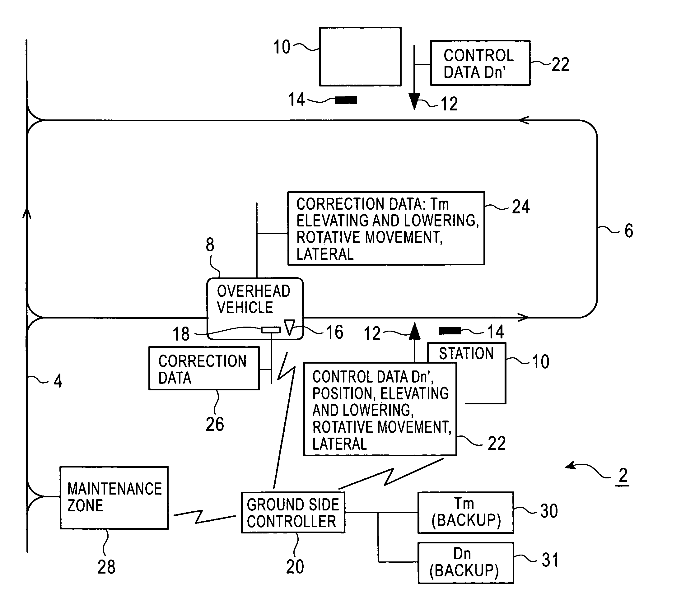
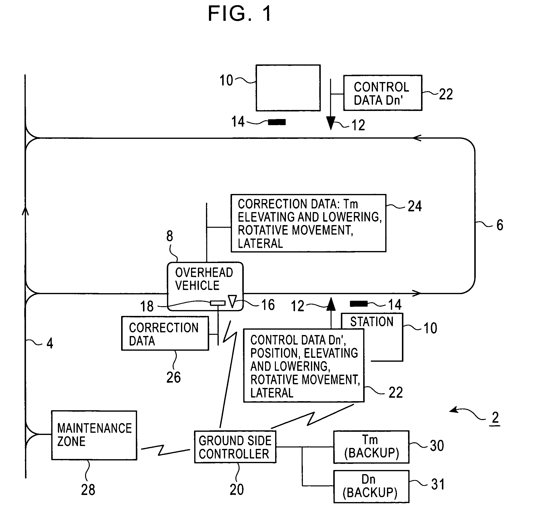
[0018]FIGS. 1 to 5 show an embodiment. The embodiment describes an overhead vehicle by way of example but other carriages may be used. FIG. 1 shows the layout of an overhead vehicle system 2. A running route for an overhead vehicle 8 includes an inter-bay route 4 and an intra-bay route 6. Stations 10 such as load ports for semiconductor processing devices are provided along the routes 4, 6. 12 is an ID tag that uses a bar code or the like to describe stoppage control data that uses a detected mark 14 described later as a reference and transfer control data. The detected mark 14 is provided in front of the station 10 or between the station and a stopped position. The overhead vehicle 8 is provided with an ID reader 16 to read the stoppage or transfer control data from the ID tag 12. The overhead vehicle 8 is also provided with a linear sensor 18 to detect the absolute position of the linear sensor 18...


PUM


Abstract

An ID tag describing control data on a stopped position for each station 10, movement required for a transfer, and the like is installed in front of the station 10. An overhead vehicle 8 reads the control data and uses it for stoppage and transfer. The overhead vehicle 8 need not store the stoppage or transfer control data for each station 10. Further, the control data can be changed without updating the storage in the overhead vehicle 8.

Description

FIELD OF THE INVENTION[0001]The preset invention relates to a carriage system with an overhead vehicle, a rail guided vehicle, or a stacker crane, and in particular, to the teaching of control data concerning stopped positions and transfers. In the specification, the term stoppage control data refers to data on a position at which a carriage is stopped at a station. The term transfer control data refers to data on the amount by which each section of a transfer device moves during a transfer of an article to or from a station. The term ground side is used in contrast with a carriage side and means stations (stopped positions), a running rail, and a ground side controller for the carriage system.BACKGROUND OF THE INVENTION[0002]The Japanese Patent Publication No. 3367389 discloses calibration of overhead vehicles and stations in an overhead vehicle system. A large-scale system has at least 100 overhead vehicles and several hundred stations (stopped positions). When stoppage or transfe...

Claims


Application Information

Patent Timeline
Patent Type & Authority Patents(United States)
IPC IPC(8): H04N1/04B61B13/00B61B3/02B61L3/00B61L23/00B65G1/04B66C7/16B66C13/00B66C13/46B66F9/07G05D1/02
CPCB61B3/02G05D1/0265G05D1/0234B61L23/005B66C7/16B66C13/46B66C13/00
Inventor HORI, KIKUONAKAO, TAKASHIOSHIUMI, KOICHIROISHURA, AKIHIKO
Owner MURATA MASCH LTD
Why Eureka
Eureka Blog
Learn More