
Ink supply device, ink jet recording apparatus and ink cartridge

a technology of ink jet recording apparatus and ink cartridge, which is applied in printing and other directions, can solve the problems of ink leakage, ink leakage, and ink deterioration, and achieve the effects of preventing ink leakage, preventing leakage of ink, and keeping the pressure inside the recording head approximately constan

Inactive Publication Date: 2010-01-19
FUJIFILM CORP
View PDF8 Cites 48 Cited by
  • Summary
  • Abstract
  • Description
  • Claims
  • Application Information

AI Technical Summary

Benefits of technology

[0008]In view of the foregoing, a primary object of the present invention is to provide an ink supply device for supplying ink from an ink container, which contains the ink in an ink bag, to a recording head of an ink jet recording apparatus, so that the ink supply device ensures stability of ink-discharging from the recording head and prevents ink leakage from the recording head during the recording.
[0020]Because the ink supply amount adjusting device is controlled to supply the recording head with the ink by an amount corresponding to the discharged ink amount, the pressure inside the recording head is kept approximately constant, so the stability of ink-discharging operation of the recording head is improved, while preventing leakage of the ink during the printing.
[0021]The same effect is obtained by measuring the pressure inside the recording head and controlling the ink supply amount adjusting device in accordance with the measured pressure.

Problems solved by technology

If the ink is exposed to air, the air will be dissolved in the ink, forming air bubbles in the ink, or some components of the ink react with oxygen, deteriorating the ink.
However, because the above prior art keeps the ink supply path open during the recording, there remain some concerns about stability of ink-discharging and ink leakage during the recording.

Method used


Image

  • Ink supply device, ink jet recording apparatus and ink cartridge
  • Ink supply device, ink jet recording apparatus and ink cartridge
  • Ink supply device, ink jet recording apparatus and ink cartridge

Examples


first embodiment

[0068]Although the first embodiment uses the valve unit as the ink supply amount adjusting device, a pump is usable as an ink supply amount adjusting device instead.

[0069]As described so far, in order to suppress variations in the head internal pressure, the first embodiment determines the ink level based on the discharged amount of ink from the recording head, calculates from the ink level the flow rate through the ink supply amount adjusting device, and controls the ink supply amount adjusting device to supply the recording head with the ink by an amount corresponding to the discharged ink amount. It is alternatively possible to measure the head internal pressure, and control the ink supply amount adjusting device so as to keep the head internal pressure in a predetermined set value.

second embodiment

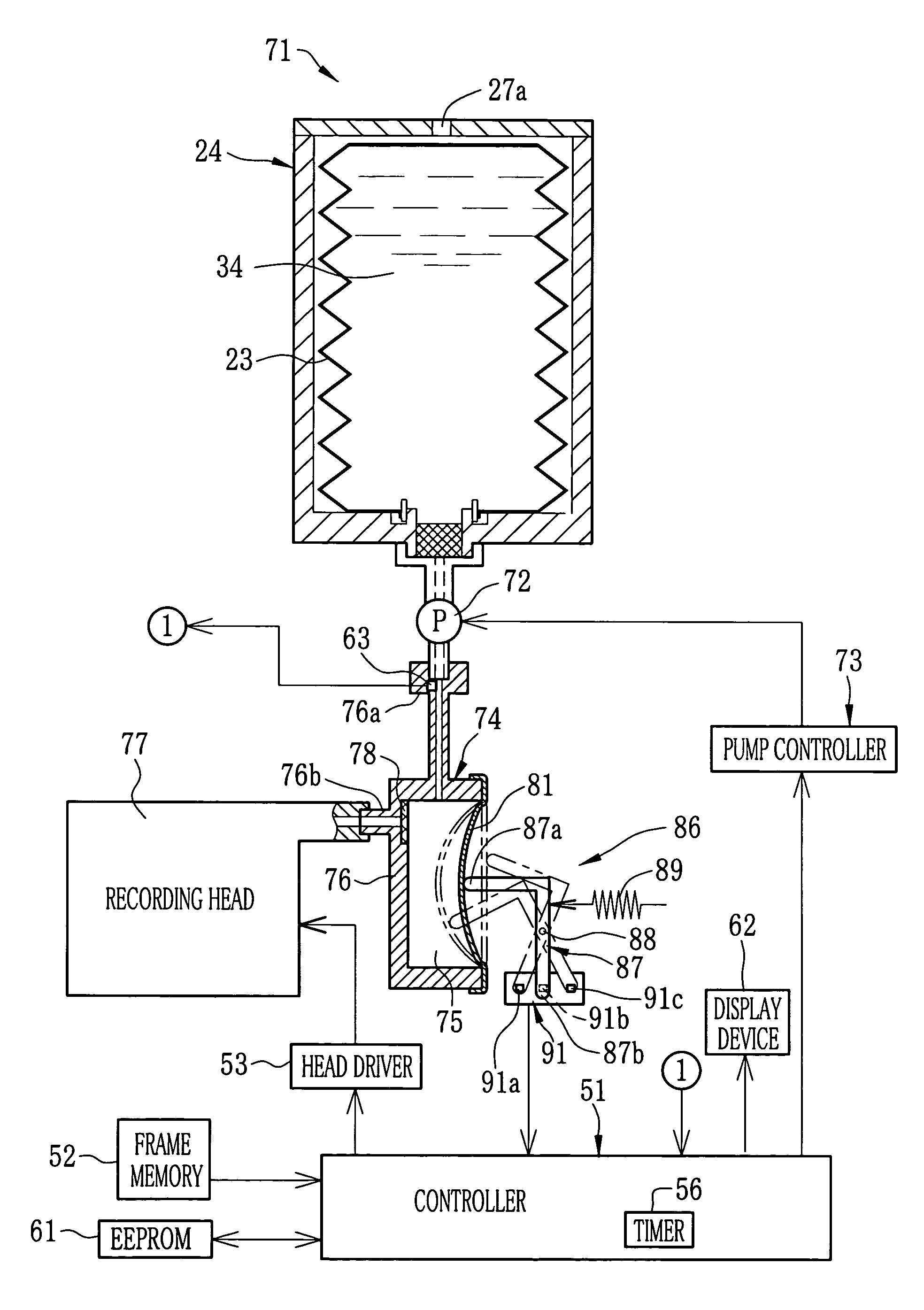
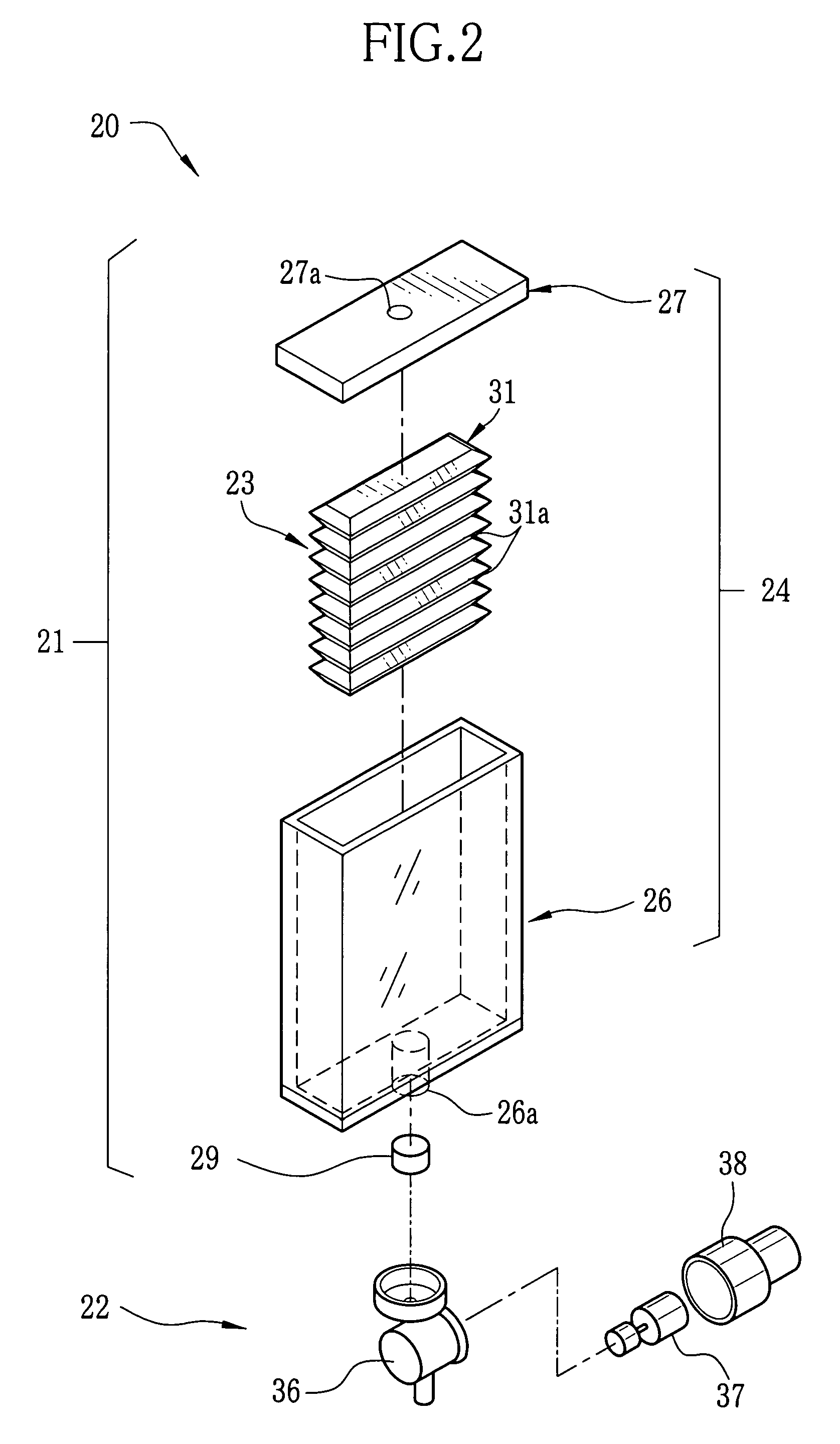
[0070]FIG. 11 shows a second embodiment that measures the head internal pressure to control an ink supply amount adjusting device. An ink cartridge 71 is provided with a suction pump 72 as the ink supply amount adjusting device, instead of a valve unit. The suction pump 72 sucks the ink out of the ink bag 23, and sends it forcibly to downstream, so the amount of ink residue in the ink bag 23 is finally reduced. In the following embodiments, equivalent components are designated by the same reference numerals, to avoid redundant description of these components.

[0071]A controller 51 controls the suction pump 72 through a pump controller 73. Upon the suction pump 72 being activated, the ink begins to be supplied to a recording head 12. When the suction pump 72 is deactivated, the ink supply is stopped. Therefore, the amount of ink supplied to the recording head 12 is determined by the operation time of the suction pump 72. The suction pump 72 may be mounted to a case 24 of the ink cartr...

third embodiment

[0084] shown in FIG. 14, a head internal pressure detecting mechanism 86 is used merely for the initial adjustment of the head internal pressure. In order to adjust the head internal pressure during the printing, a valve unit 22 is controlled as an ink supply amount adjusting device to supply the ink to a recording head 12 in accordance with the discharged amount of ink. As shown in FIG. 15, first the head internal pressure detecting mechanism 86 detects the sub-tank pressure, and carries out the initial adjustment of the head internal pressure. After the start of printing, the discharged amount of ink is measured for example by estimation based on the image data, and the ink level H is detected based on the discharged ink amount. Taking account of the ink level H, a controller 51 calculates the flow rate Q through the valve unit 22, and controls the valve opening time of the valve unit 22 based on the flow rate Q, so as to supply the recording head 12 with the ink by an amount corr...


PUM


Abstract

An ink cartridge consists of an ink bag storing ink and a case holding the ink bag. A valve unit is placed on an ink supply path from the ink bag to a recording head. During the printing, the amount of ink discharged from the recording head is measured at predetermined time intervals, and the valve unit is controlled to supply the recording head with the ink by an amount corresponding to the discharged amount. So the pressure inside the recording head is kept approximately constant, improving stability of ink-discharging from nozzles of the recording head. A head internal pressure detecting mechanism detects pressure inside a sub-tank as a value representative of the head internal pressure.

Description

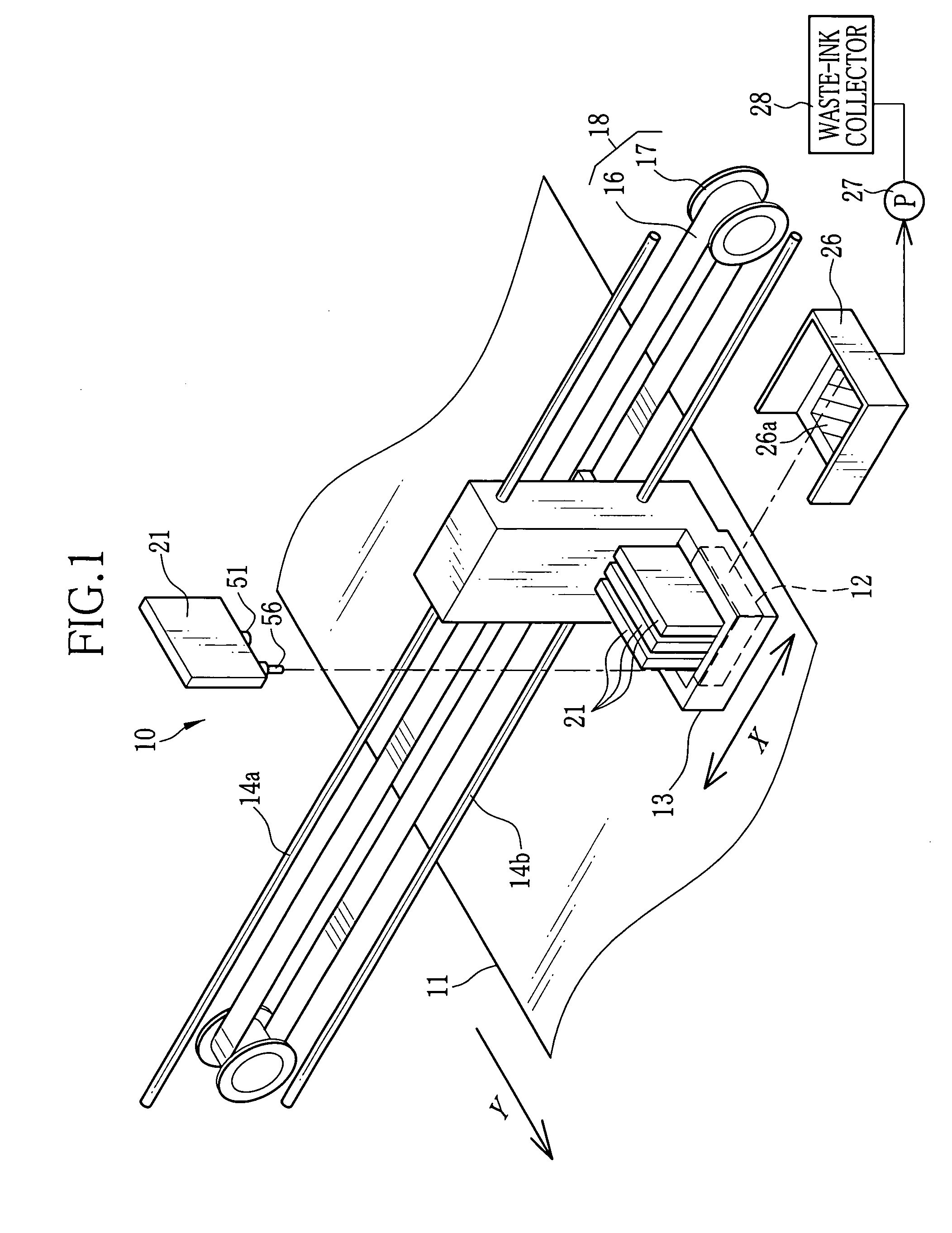
FIELD OF THE INVENTION[0001]The present invention relates to an ink supply device for supplying ink to an ink jet type recording head. The present invention relates also to an ink jet recording apparatus using the ink supply device, and an ink cartridge removably mounted in the ink jet recording apparatus, such that the ink is supplied from the ink cartridge to the recording head through the ink supply device.BACKGROUND ARTS[0002]An ink jet recording apparatus has been known, which has a recording head for discharging ink as droplets onto a recording paper to print an image. The ink jet recording apparatus is provided with at least an ink container containing ink, to supply the ink from the ink container to the recording head. In an example, the recording head is provided with at least a nozzle and an oscillation plate driven by a piezoelectric element. Making use of pressure change in the nozzle, which is caused by oscillating the oscillation plate, the ink is supplied from the ink...

Claims


Application Information

Patent Timeline
Patent Type & Authority Patents(United States)
IPC IPC(8): B41J2/175
CPCB41J2/17566B41J2002/17516B41J2002/17569
Inventor KACHI, YASUHIKO
Owner FUJIFILM CORP
Learn More