
Irrigation mat and method of use

a technology of irrigation mats and mats, which is applied in the field of irrigation mats, can solve the problems of too much water supplied, rigid water supply pipes, and the need for mats to be assembled on site, and achieve the effect of convenient installation

Active Publication Date: 2010-01-19
UNIV LAVAL
View PDF17 Cites 17 Cited by
  • Summary
  • Abstract
  • Description
  • Claims
  • Application Information

AI Technical Summary

Benefits of technology

The present invention provides an improved irrigation mat that overcomes the disadvantages of prior art. The mat includes a base sheet, a water permeable top sheet, and a capillary mat with high capillary properties and a fluffy textile top layer material. The mat can be easily installed over a ground surface or a hard support surface and is easy to roll up for shipping and storage. The mat allows for the placement of drip tapes in any desired location between the top sheet and the capillary mat. The drip tape is a hollow flat tube constructed of perforated plastics material and extends between the open ends of the mat. The mat is capable of being rolled upon itself with the drip tapes therein.

Problems solved by technology

A disadvantage of such an irrigation mat is that the mat must be assembled on site with rigid water supply pipes.
The construction of the mat is also expensive as one needs to stitch channels at spaced apart intervals within the mat.
Often there are too many channels and too much water supplied to the mat.
This is a time-consuming job.
Also, these pipes cause the mat to bulge on the top surface thereof making that part of the mat non-usable for laying pots thereover.
Accordingly, it is not practical for use in nurseries.
Finally, installation of very long capillary mats in the field or on greenhouses benches is not recommended, as plant root diseases may spread over large surfaces.
Also, water may drain from upward to downward position, increasing the risk of non-uniform water distribution between pots.
However, placing smaller pieces of mat together in a uniform assemblage is time and resources consuming and not practical in nurseries and greenhouses.

Method used


Image

  • Irrigation mat and method of use
  • Irrigation mat and method of use
  • Irrigation mat and method of use

Examples


Embodiment Construction

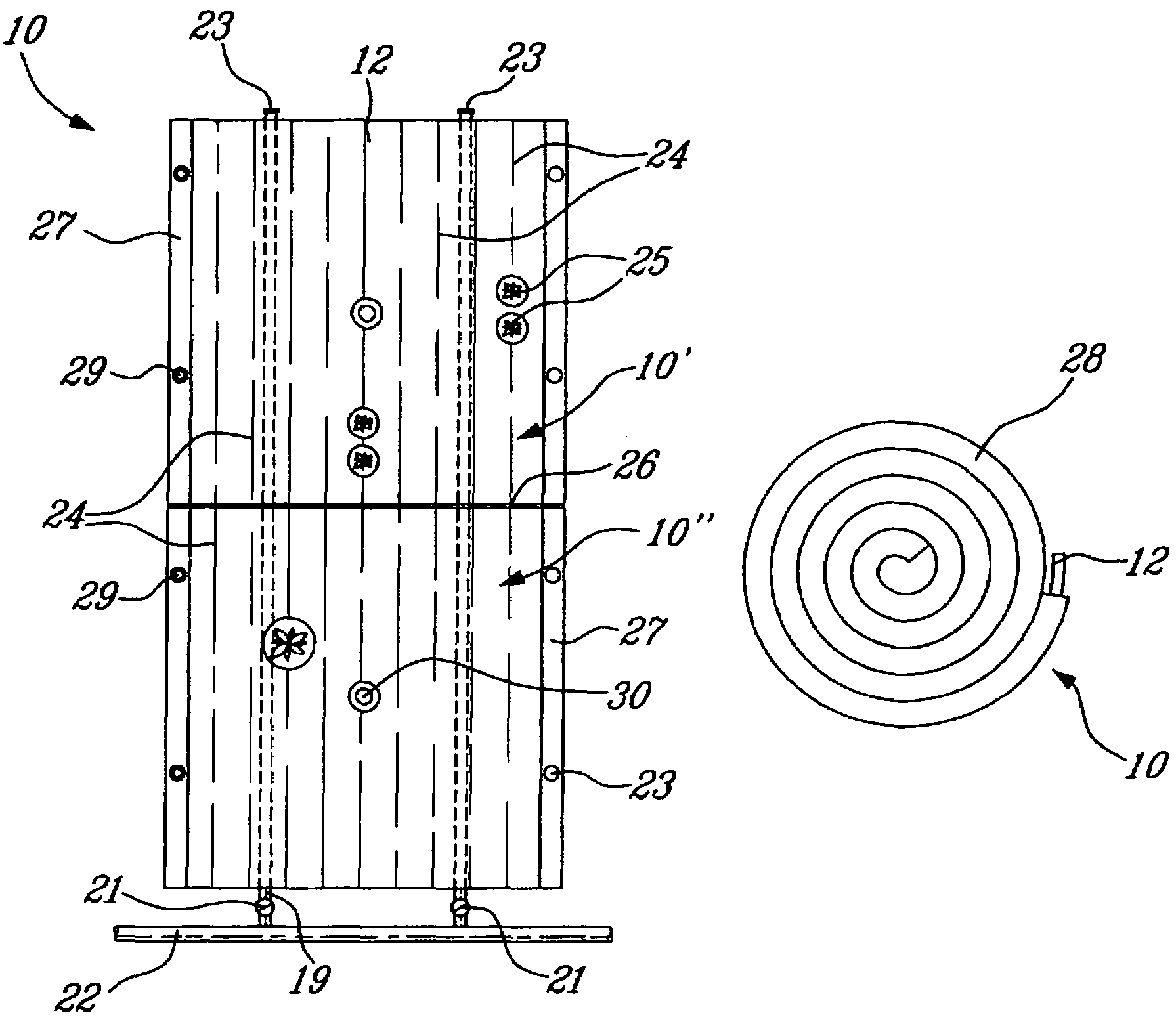
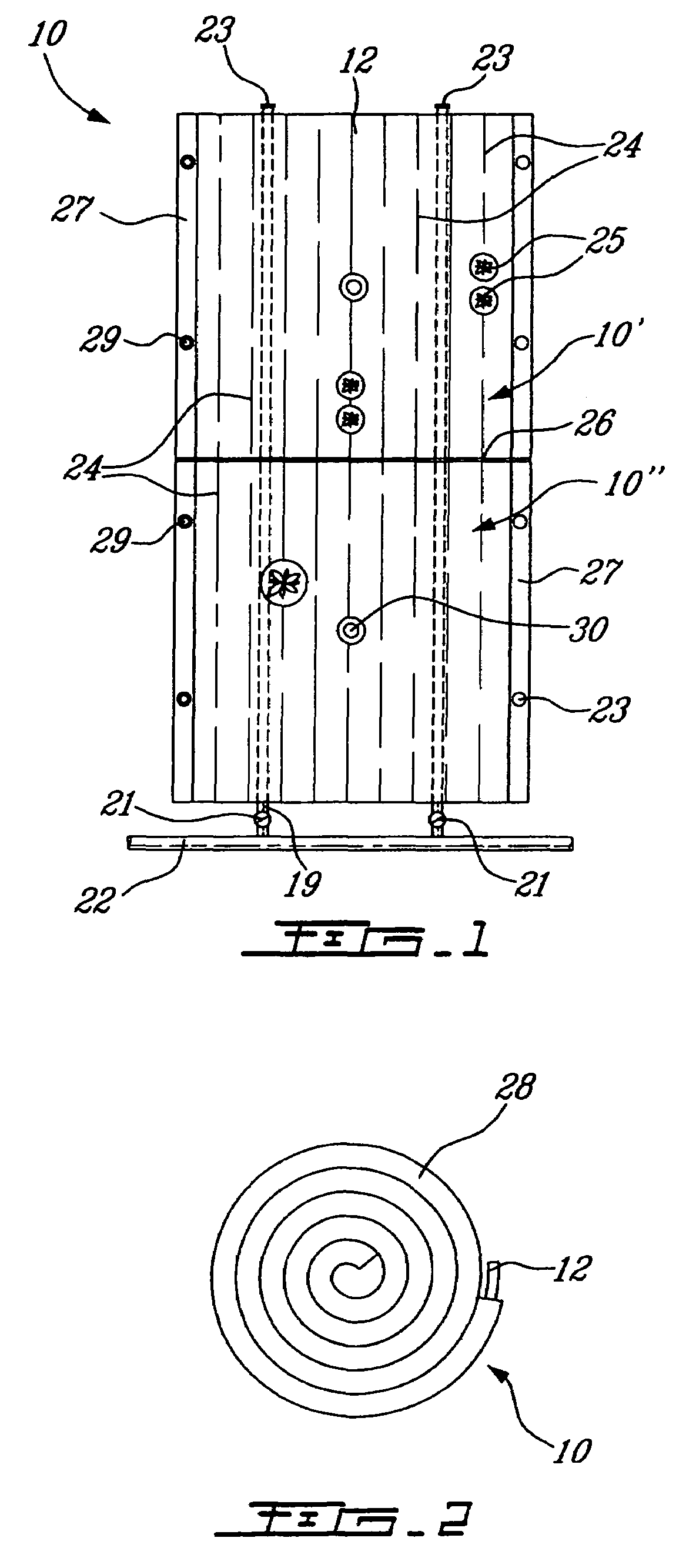
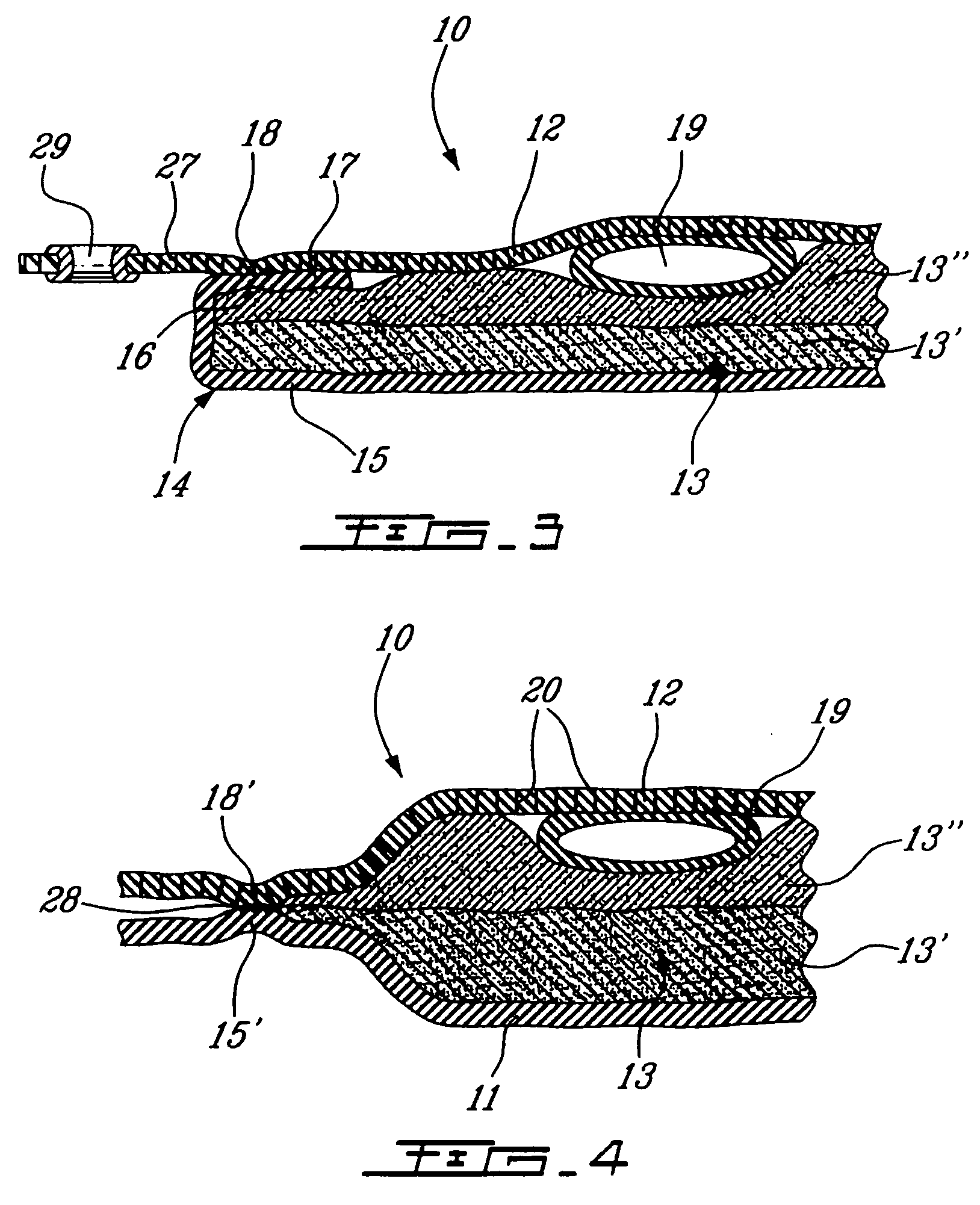
[0015]Referring to FIGS. 1 to 4, there is shown generally at 10, the irrigation mat of the present invention. It is comprised of a water impermeable base sheet 11. Sheet 11 may alternatively have holes or slits in an amount small enough to allow a very slow seepage of water from the mat to the ground but the holes are not large enough to allow a good contact with the underneath soil. A water permeable top sheet 12 and a capillary mat 13 disposed between the base sheet and the top sheet. The capillary mat has a bottom absorbent material 13′ having high capillary properties whereby to permit circulation of water in all directions therein. The top part of the capillary mat is a compressible material, herein a fluffy textile layer 13″ which is bonded to the absorbent material 13′, either by needle stitching or otherwise and separates the bottom absorbent material from the top sheet 12. The top sheet 12 has holes therein in the range of from about 10 to 50 microns to allow proper capilla...


PUM


Abstract

An irrigation mat is comprised of a water impermeable base sheet, a water permeable top sheet and a capillary mat disposed between the base sheet and the top sheet. One or more flat pliable optional drip tapes are loosely disposed between the top sheet and the capillary mat and displaceable therebetween to any desirable position. The drip tape is a hollow flat tube constructed of perforated plastics material and extends at least a full length of the irrigation mat. The irrigation mat with the drip tapes is capable of being rolled up upon itself to form a roll. The top sheet is also heat fused to the folded edges of the back sheet.

Description

TECHNICAL FIELD[0001]The present invention relates to an irrigation mat comprised of a base sheet, a water permeable top sheet and a capillary mat sandwiched therebetween together with one or more optional flat pliable drip tapes disposed loosely over the capillary mat and which act as water conduits to supply water to the capillary mat and wherein the mat (and optional drip tapes) that can be rolled together in a bundle.BACKGROUND ART[0002]Reference is made to PCT Application WO 2004 / 056172 filed Dec. 23, 2002 and relating to an irrigation mat for irrigating potted plants. Water is supplied to the irrigation mat by overhead sprinklers and the mats absorb and retain water and feed the potted plants through holes formed at the bottom of the pots. The present invention is an improvement of this type of irrigation mat.[0003]There is further described in U.S. Pat. No. 5,839,659 a capillary root zone irrigation system utilizing an irrigation mat. The irrigation mat is also provided with ...

Claims


Application Information

Patent Timeline
Patent Type & Authority Patents(United States)
IPC IPC(8): A01G9/24
CPCA01G25/06A01G2025/003A01G27/04
Inventor CARON, JEANPEPIN, FRANCOISTHEORET, RICHARD
Owner UNIV LAVAL
Learn More