
Door-stopping device for motor vehicles

a technology for stopping devices and motor vehicles, which is applied in the direction of door/window fittings, multi-purpose tools, construction, etc., can solve the problems of considerable structural limitations, weight disadvantages, and structural limitations of the design of the stopping device and the associated components, and achieves high reliability, low cost, and increased locking positions

Inactive Publication Date: 2010-01-05
ISE INNOMOTIVE SYST EURO
View PDF18 Cites 29 Cited by
  • Summary
  • Abstract
  • Description
  • Claims
  • Application Information

AI Technical Summary

Benefits of technology

"The invention is a door-stopping device that offers multiple possibilities of configuration, can be manufactured in a cost-effective manner, and occupies minimal space. The device includes a spring system that allows for the locking levers to be positioned in relation to the door holder bar in a way that is independent of the pivoting axis of the door holder bar. The locking levers can be oriented in different directions, and the design offers the advantage of being able to adapt to different vehicle structures without requiring a complete overhaul of the device. The invention also includes a design with asymmetrical locking grooves that allow for different forces for opening and closing the door, and a design with circular cross-section locking elements and arcuate locking grooves that ensures reliable stopping of the vehicle door in the opening positions. The locking elements can be formed as an integral part of the locking levers, reducing manufacturing costs."

Problems solved by technology

This door-stopping device has the drawback that its function absolutely requires that the locking grooves must be oriented parallel to the pivoting axis of the door holder bar associated with the vehicle body, since a pivoting ability of the door holder bar is the prerequisite for the operation of the locking unit.
This results in considerable structural limitations in the design of the stopping device as well as the associated components, i.e. the vehicle door and the fixing regions of the door holder bar on the vehicle body.
This, however, entails considerable structural limitations as well as disadvantages with regard to weight.

Method used


Image

  • Door-stopping device for motor vehicles
  • Door-stopping device for motor vehicles
  • Door-stopping device for motor vehicles

Examples


Embodiment Construction

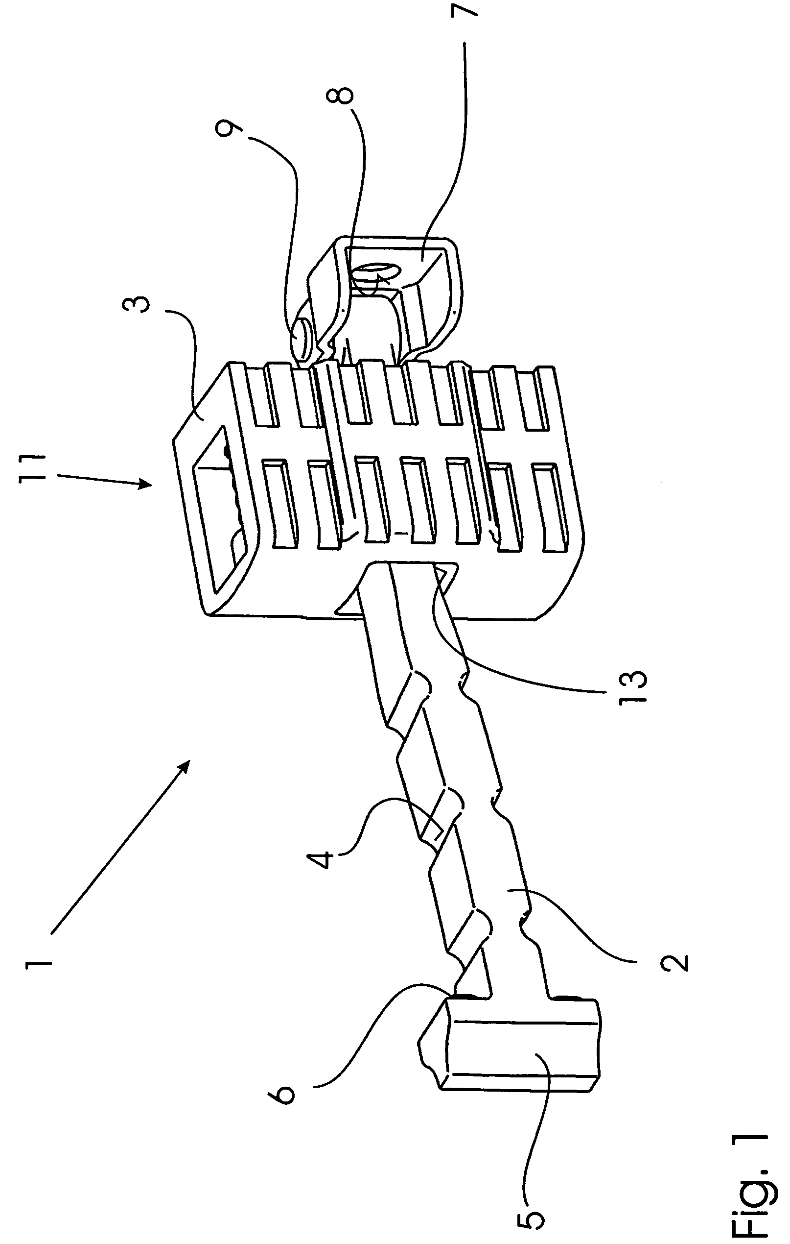
[0039]FIG. 1 shows a first embodiment of a door-stopping device 1 made predominantly of plastics.

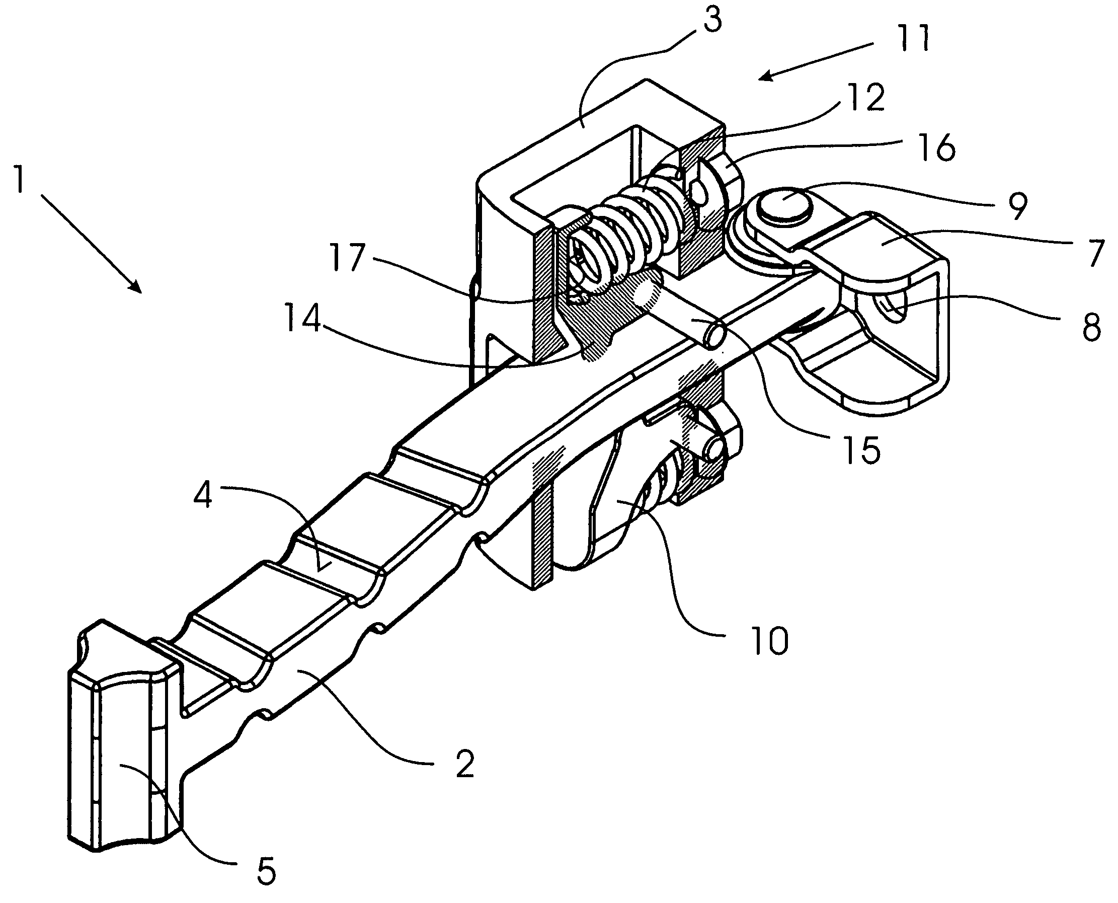
[0040]A door holder bar 2 of the door-stopping device 1, formed by a metal rod coated with plastics, is, on the one hand, connected in an articulated manner to a pillar bracket 7 by a bolt 9. The door holder bar 2 may be fitted pivotally to a vehicle body, not shown here, by way of the pillar bracket 7, comprising an aperture 8 for receiving a fastening screw, not shown here. The door holder bar 2 is disposed in a passage 13 of a support housing 3 which may be fitted to a vehicle door, likewise not shown here. Should the vehicle door be pivoted in relation to the vehicle body, the support housing 3 fitted to the vehicle door is displaced relatively in relation to the door holder bar 2, in which case the door holder bar 2, in order to provide a maximum opening angle of the vehicle door, comprises a stopping member 5 at its end facing the vehicle door, which stopping member 5, at its side ...


PUM


Abstract

A door-stopping device for motor vehicles, includes a door holder bar, a support housing including a passage for the door holder bar to pass through, and a locking unit disposed in the support housing, which includes two pivotally mounted locking levers. Each locking lever is pre-tensioned by a spring element towards each other and towards the door holder bar. Each locking lever comprises a locking element. The locking elements bear on mutually opposite sides against the door holder bar and are adapted to engage with the locking grooves on the door holder bar. For the door-stopping device to present diverse possibilities of design, to be manufactured in a cost-effective manner and to occupy only little space, the spring elements are arranged substantially parallel to the door holder bar.

Description

BACKGROUND[0001](1) Field of the Invention[0002]The invention relates to a door-stopping device for motor vehicles comprising a door holder bar, a support housing with a passage for the door holder bar to pass through and a locking unit provided in the support housing, comprising two pivotally mounted locking levers, each pre-tensioned by a spring element towards each other and towards the door holder bar, each locking lever comprising a locking element, the locking elements bearing on mutually opposite sides against the door holder bar and being adapted to engage with the locking grooves on the door holder bar.[0003](2) Prior Art[0004]A door-stopping device is known from DE 201 20 271 U1, wherein a door holder bar, provided with locking grooves, is arranged pivotally on a vehicle body on the one hand, and in a displaceable manner in the support housing fitted to the vehicle door on the other hand. When the vehicle door is pivoted, a lateral face of the door holder bar provided with...

Claims


Application Information

Patent Timeline
Patent Type & Authority Patents(United States)
IPC IPC(8): E05C17/22
CPCE05C17/203Y10T16/54028Y10T16/6295
Inventor LOWEN, JAKOBKUMOR, GYALA
Owner ISE INNOMOTIVE SYST EURO
Learn More