
Washing and drying machine

a technology of washing machine and washing machine, which is applied in the direction of washing machine with receptacles, other washing machines, textiles and papermaking, etc., can solve the problems of increasing and achieve the reduction of flow resistance, reducing water consumption, and reducing the maintenance cost of the conventional washing and drying machine

Active Publication Date: 2009-12-22
LG ELECTRONICS INC
View PDF20 Cites 9 Cited by
  • Summary
  • Abstract
  • Description
  • Claims
  • Application Information

AI Technical Summary

Benefits of technology

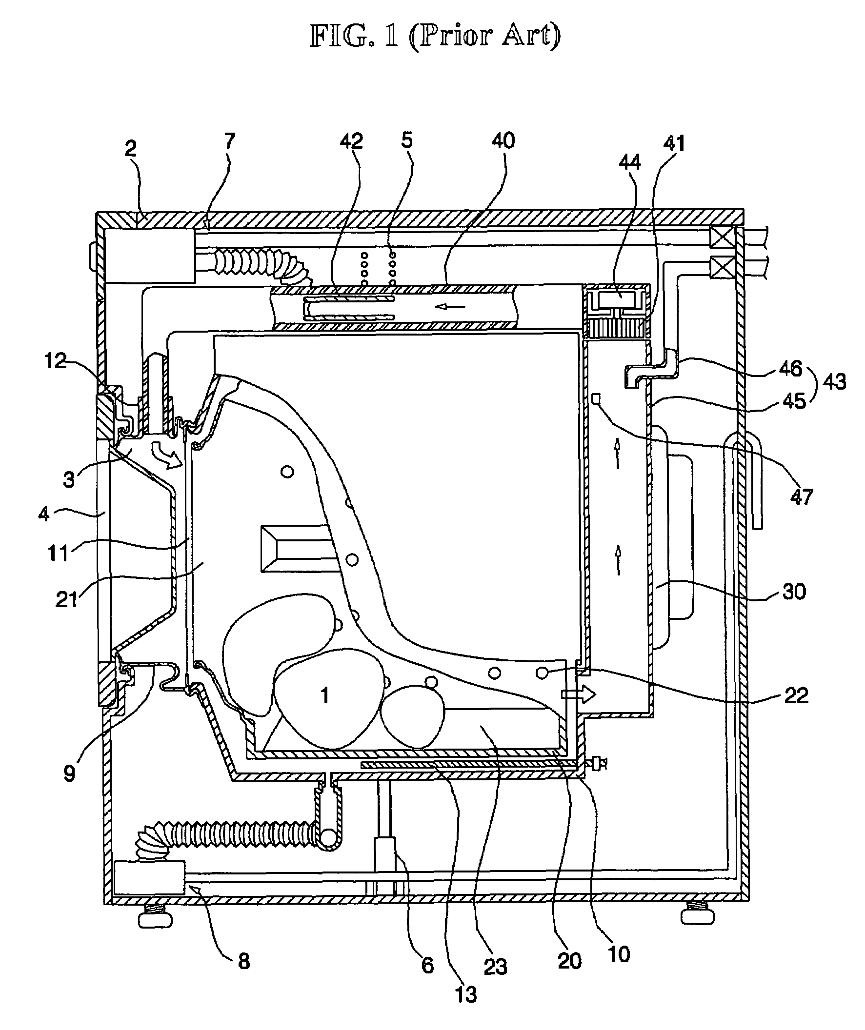
[0033]The present invention is provided in view of the above problems, and it is an object of the present invention to provide a washing and drying machine that is capable of condensing air used to dry laundry with outside air without use of cooling water, thereby minimizing flow resistance, improving drying efficiency, and reducing maintenance costs.
[0037]Preferably, the air-cooling type condensing unit further includes: a condensing plate mounted in the condensing channel for facilitating heat exchange between the outside air and the inner circumferential surface of the tub.
[0041]Preferably, the air-cooling type condensing unit further includes: a condensing plate mounted at the circumferential surface of the tub for facilitating heat exchange between the outside air and the circumferential surface of the tub.
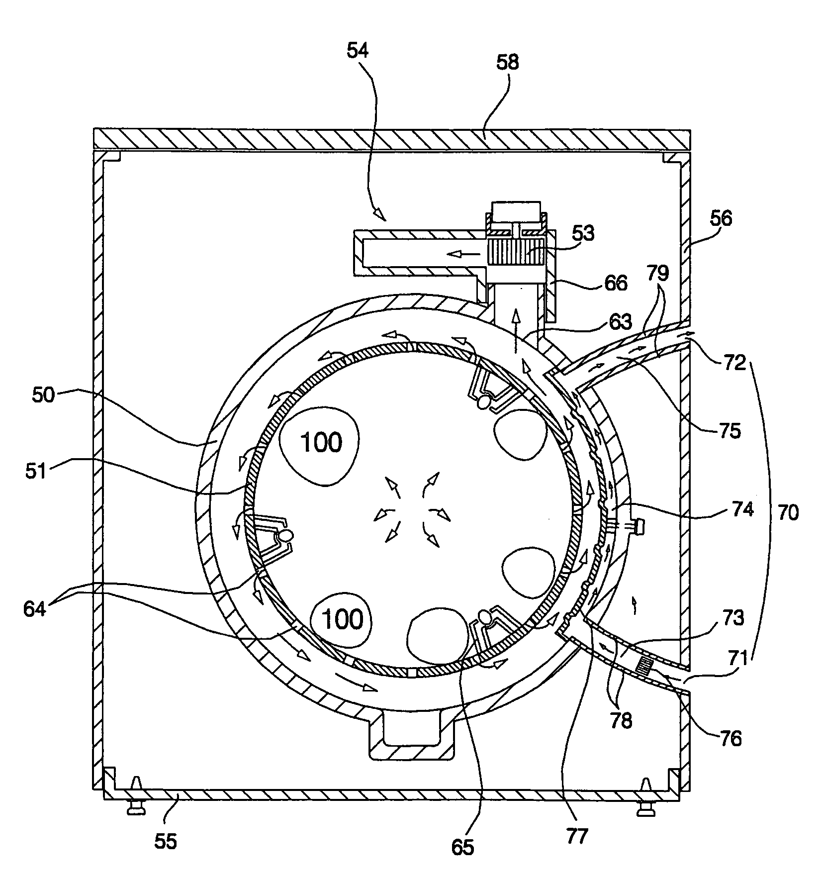
[0044]According to the present invention, the outside air exchanges heat with the circumferential surface of the tub to condense air used to dry the laundry. As a result, no cooling water is used to condense air used to dry the laundry. Consequently, the present invention has the effect of reducing consumption of water, and therefore, decreasing the maintenance costs of the washing and drying machine.
[0045]Furthermore, no condensing duct is necessary. Consequently, flow resistance is decreased, and therefore, drying efficiency is improved. In addition, sufficient space is provided between the rear surface of the tub and the cabinet. Consequently, the present invention has the effect of increasing the volume of the drum, and therefore, increasing the washing / drying capacity of the washing and drying machine.

Problems solved by technology

Furthermore, a great amount of cooling water is consumed to cool the condensing duct 45, and therefore, the maintenance costs of the conventional washing and drying machine are increased.

Method used


Image

  • Washing and drying machine
  • Washing and drying machine
  • Washing and drying machine

Examples


first embodiment

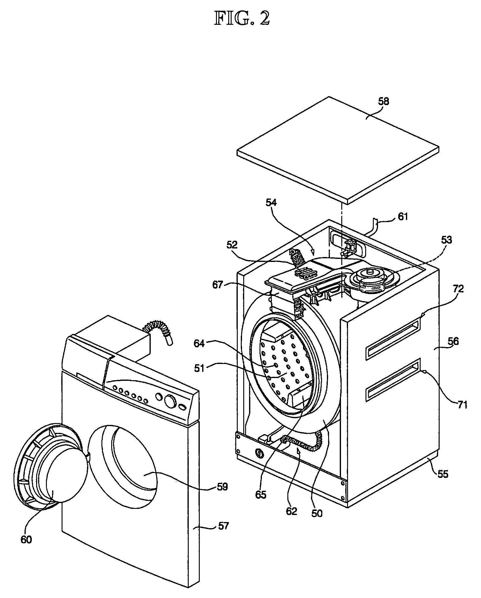
[0056]As shown in FIGS. 2 to 4, the washing and drying machine according to the present invention includes: a tub 50 provided in a cabinet in a suspended manner; a drum 51 rotatably disposed inside the tub 50; a drying duct 54, having a drying heater 52 and a circulating fan 53, for supplying hot air into the drum 51 to dry laundry 100; and an air-cooling type condensing unit 70 for performing heat exchange between air introduced from the outside of the cabinet and the circumferential surface of the tub 50 to condense air used to dry the laundry 100 in the drum 51.

[0057]The cabinet includes: a base pan 55; a cabinet body 56 mounted on the base pan 55; a cabinet cover 57 disposed in the front of the cabinet body 56; and a top plate 58 mounted on the cabinet body 56 and the cabinet cover 57.

[0058]At the cabinet cover 57 is formed a laundry inlet / outlet hole 59, through which the laundry 100 is placed into or removed from the drum 51. To the cabinet cover 57 is also pivotably attached ...

second embodiment

[0089]FIG. 5 is a cross-sectional view illustrating a washing and drying machine according to the present invention.

[0090]The washing and drying machine according to the second embodiment of the present invention includes an air-cooling type condensing unit 80. As shown in FIG. 5, the air-cooling type condensing unit 80 includes: an inlet port 81 formed at one side of the cabinet body 56 for allowing outside air to be introduced into the cabinet therethrough; an outlet port 82 formed at the other side of the cabinet body 56 for allowing the outside air, which has exchanged heat with the circumferential surface of the tub 50, to be discharged out of the cabinet therethrough; and a condensing channel 83 defined by the inside surface of the cabinet body 56 and the outer circumferential surface of the tub 50 for allowing the outside air introduced through the inlet port 81 to flow between the outer circumferential surface of the tub 50 and the inside surface of the cabinet body 56 and t...

third embodiment

[0096]FIG. 6 is a cross-sectional view illustrating a washing and drying machine according to the present invention.

[0097]The washing and drying machine according to the third embodiment of the present invention includes an air-cooling type condensing unit. As shown in FIG. 6, the air-cooling type condensing unit includes: an inlet port 91 formed at one side of the cabinet body 56 for allowing outside air to be introduced into the cabinet therethrough; and an outlet port 92 formed at the other side of the cabinet body 56 for allowing the outside air, which has exchanged heat with the circumferential surface of the tub 50, to be discharged out of the cabinet therethrough.

[0098]In the illustrated embodiment, the inlet port 91 is formed on the right or left side surface of the cabinet body 56, and the outlet port 92 is formed on the rear surface of the cabinet body 56. Alternatively, the inlet port 91 may be formed on another surface of the cabinet body 56 such as the rear, top or fron...


PUM


Abstract

A washing and drying machine that is capable of performing heat exchange between outside air introduced into a cabinet and the circumferential surface of a tub so as to condense air used to dry laundry. No cooling water is used to condense air used to dry the laundry. Consumption of water is reduced, and therefore, the maintenance costs of the washing and drying machine are decreased. Furthermore, no condensing duct is necessary. Consequently, flow resistance is decreased, and drying efficiency is improved. In addition, sufficient space is provided between the rear surface of the tub and the cabinet. Consequently, the volume of the drum is increased, and the washing / drying capacity of the washing and drying machine is increased.

Description

CROSS-REFERENCE TO RELATED APPLICATIONS[0001]The present disclosure relates to subject matter contained in priority Korean Application No. 2005-28483, filed on Apr. 6, 2005, which is herein expressly incorporated by reference in its entirety.BACKGROUND OF THE INVENTION[0002]1. Field of the Invention[0003]The present invention relates to a washing and drying machine, and, more particularly, to a washing and drying machine that is capable of performing heat exchange between outside air introduced into a cabinet and the circumferential surface of a tub so as to condense air used to dry laundry, thereby minimizing flow resistance, improving drying efficiency, and reducing maintenance costs.[0004]2. Description of the Related Art[0005]Generally, a washing machine is a machine that is capable of removing pollutants from clothes or bedclothes (hereinafter, referred to as “laundry”) with detergent-dissolved water or pure water (hereinafter, referred to as “washing water”). Recently, a large...

Claims


Application Information

Patent Timeline
Patent Type & Authority Patents(United States)
IPC IPC(8): D06F25/00D06F29/00
CPCD06F25/00D06F58/24D06F37/267D06F39/04D06F37/26Y02B40/00
Inventor LIM, HEE TAEHONG, SANG WOOK
Owner LG ELECTRONICS INC
Learn More