
Method for manufacturing a suprastructure and a corresponding drill jig

a technology of suprastructure and drill jig, which is applied in the field of manufacturing a suprastructure and a corresponding drill jig, can solve the problems of not being able to adapt the individual shape of the jaw of the patient, the method used according to the prior art for producing such a superstructure is laborious and laborious for the patient, and achieves the effect of simple and accurate manner

Inactive Publication Date: 2009-12-15
DENTAL VISION
View PDF8 Cites 67 Cited by
  • Summary
  • Abstract
  • Description
  • Claims
  • Application Information

AI Technical Summary

Benefits of technology

[0009]The object of the invention is to overcome the abovementioned disadvantages by proposing a method that allows holes that are necessary for the placing of implants to be drilled in a very simple and accurate manner. This method has the further advantage that the production of a superstructure and its fitting on a person's jaw can be performed in a very short time.

Problems solved by technology

The method used according to the prior art for producing such a superstructure is very laborious and protracted for a patient.
If it is found that the proposed position of the implants is unsuitable because, for example, nerve bundles or blood vessels would be touched during the drilling of holes, a new or an adapted model has to be produced.
However, a disadvantage of this method is that for fitting of the superstructure part of the bone of the upper jaw or of the lower jaw has to be removed Furthermore, the prostheses placed in this way are not adapted to the individual shape of a person's jaw.

Method used


Image

  • Method for manufacturing a suprastructure and a corresponding drill jig
  • Method for manufacturing a suprastructure and a corresponding drill jig

Examples


Embodiment Construction

[0025]The invention relates in general to a method for producing a dental prosthesis which has to be fixed upon so-called, implants provided in the jawbone of a patient. Such a dental prosthesis comprises a so-called superstructure, on which artificial teeth are provided, in a manner that is known per se, and which has fixing means for fixing to the abovementioned implants. Apart from that, the invention also relates to a method for producing an aligning plate that makes it possible in a simple manner to drill very accurate holes, in which said implants are placed.

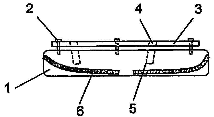
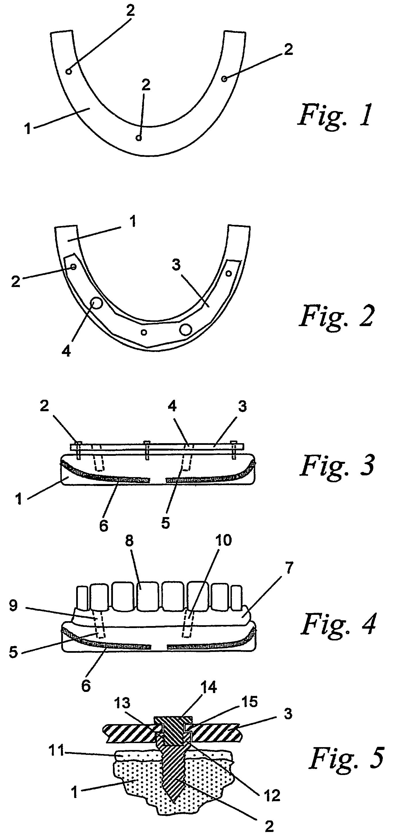
[0026]In the case of the method according to the invention, reference elements are fixed in the jaw on which the superstructure is to be placed. FIG. 1 shows diagrammatically a toothless lower jaw 1 in the case of which three reference elements have been fixed in the bone of said jaw. Each of these reference elements is formed by a screw 2.

[0027]Said screws 2 are fixed in different positions in the bone of the jaw 1, in su...


PUM


Abstract

The invention concerns a method for manufacturing a suprastructure (7) with artificial teeth (8) which is mounted on at least one implant (9,10) that is provided in the cavity of the mouth of a person and that has to be fixed to the bone of the lower jaw or the upper jaw (1), whereby a drill jig (3) is manufactured with at least one opening (4) for performing a boring (5) in the bone for mounting said implant (9,10), with the feature that the position of said opening (4) in the drill jig (3) and the position of the latter is determined in relation to at least one reference organ (2) that is fixed to said bone.

Description

BACKGROUND OF THE INVENTION[0001]1. Technical Field of the Invention[0002]The invention relates to a method for producing a superstructure provided with artificial teeth, which superstructure is fitted on at least one implant, which is provided in the oral cavity of a person and has to be fixed in the bone of a lower or an upper jaw, an aligning plate with at least one aperture being produced for the purpose of drilling a hole in the bone through said aperture, in order to fit the abovementioned implant.[0003]2. Prior Art[0004]The method used according to the prior art for producing such a superstructure is very laborious and protracted for a patient. In a first step, a wax model of a dental prosthesis is made using an impression that is taken of the patient's jaw. A replica of this wax model is then prepared in synthetic resin, in which replica openings are already provided, corresponding to a possible position for the implants, for the purpose of drilling holes in the jaw. A so-ca...

Claims


Application Information

Patent Timeline
Patent Type & Authority Patents(United States)
IPC IPC(8): A61C13/225A61C8/00A61B17/16A61C1/08A61C13/00A61C13/007A61C13/01
CPCA61C1/084B33Y80/00
Inventor DE CLERCK, RENE
Owner DENTAL VISION
Learn More