
Industrial truck with a camera device

a camera device and industrial truck technology, applied in the field of industrial trucks, can solve the problems of driver and camera not being able to navigate solely on the basis of the image displayed on the screen, and the camera cannot view the entire area behind the industrial truck

Inactive Publication Date: 2009-12-08
STILL GMBH
View PDF22 Cites 120 Cited by
  • Summary
  • Abstract
  • Description
  • Claims
  • Application Information

AI Technical Summary

Benefits of technology

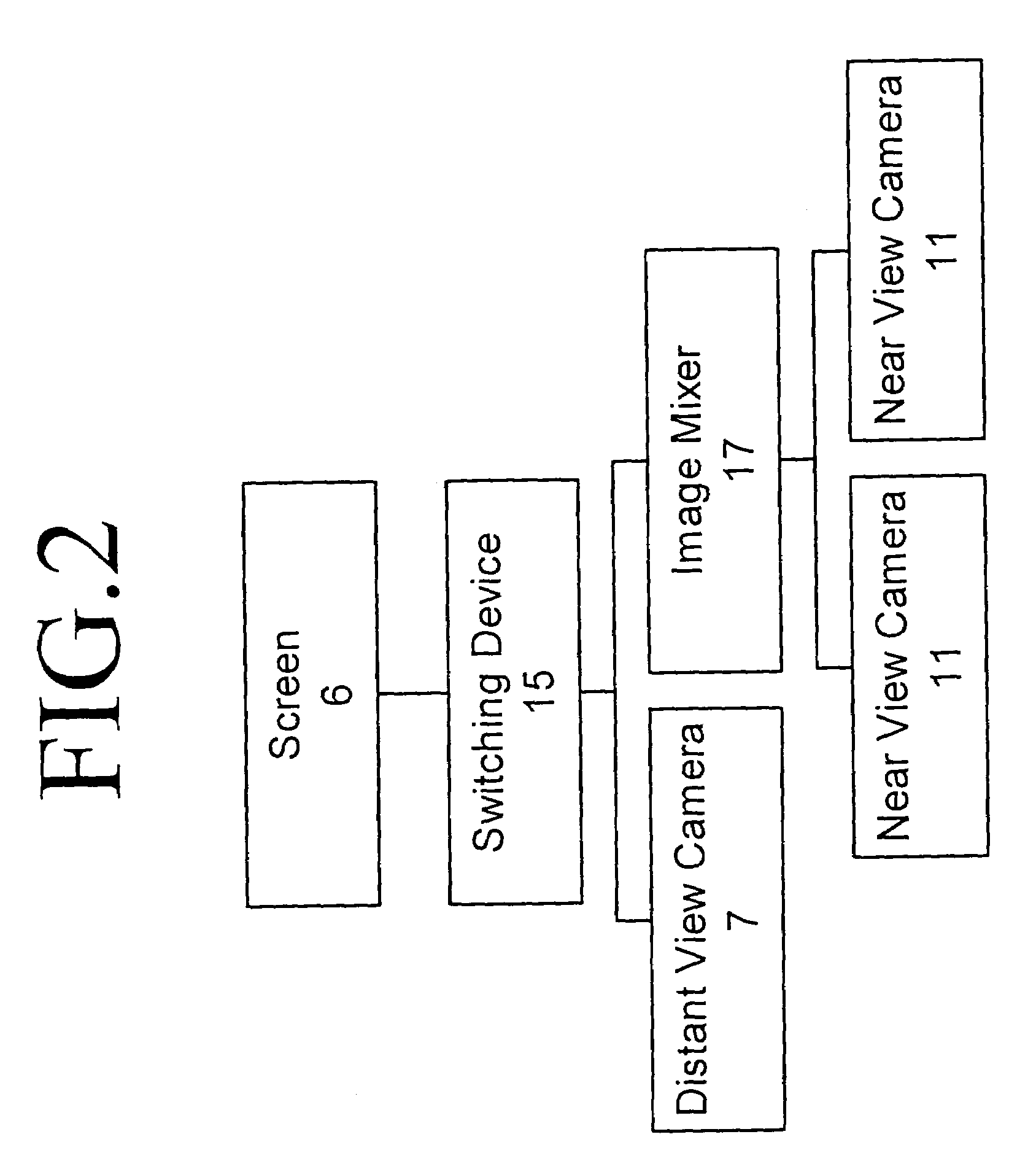
[0011]It is particularly advantageous if there are two additional cameras that can be used to view the near area. It thereby becomes possible to completely eliminate any blind spots behind the industrial truck that cannot be viewed with the cameras.
[0015]It is also possible that the screen can be effectively connected with an image mixer, by which the near area viewed by the first camera and the distant area viewed by the at least one additional camera can be displayed on the screen simultaneously. There is no need to switch manually between the near and distant areas, because with this type of arrangement the driver can observe both views simultaneously and next to each other on the screen.
[0018]It is advantageous if the screen is located inside the driver's cab in the vicinity of the legroom for the driver. For example, the screen can be located between the driver's legs in the forward portion of the driver's cab. The screen thereby does not interfere with the driver's view or access to the display and control elements in the vicinity of the dashboard.
[0019]It is advantageous if the industrial truck has a steering device with an electrical steering sensor. Steering sensors of this type do not require a steering column, which would interfere with the installation of the screen in the area between the driver's legs.

Problems solved by technology

One problem with industrial trucks of the prior art that are equipped with a camera and screen to facilitate travel in reverse is that the camera cannot view the entire area behind the industrial truck.
Even equipping the camera with an extreme wide-angle lens cannot completely eliminate this problem, because in that case, the image displayed on the screen is severely distorted in the peripheral areas, which means that the driver cannot navigate solely on the basis of the image displayed on the screen.

Method used


Image

  • Industrial truck with a camera device
  • Industrial truck with a camera device
  • Industrial truck with a camera device

Examples


Embodiment Construction

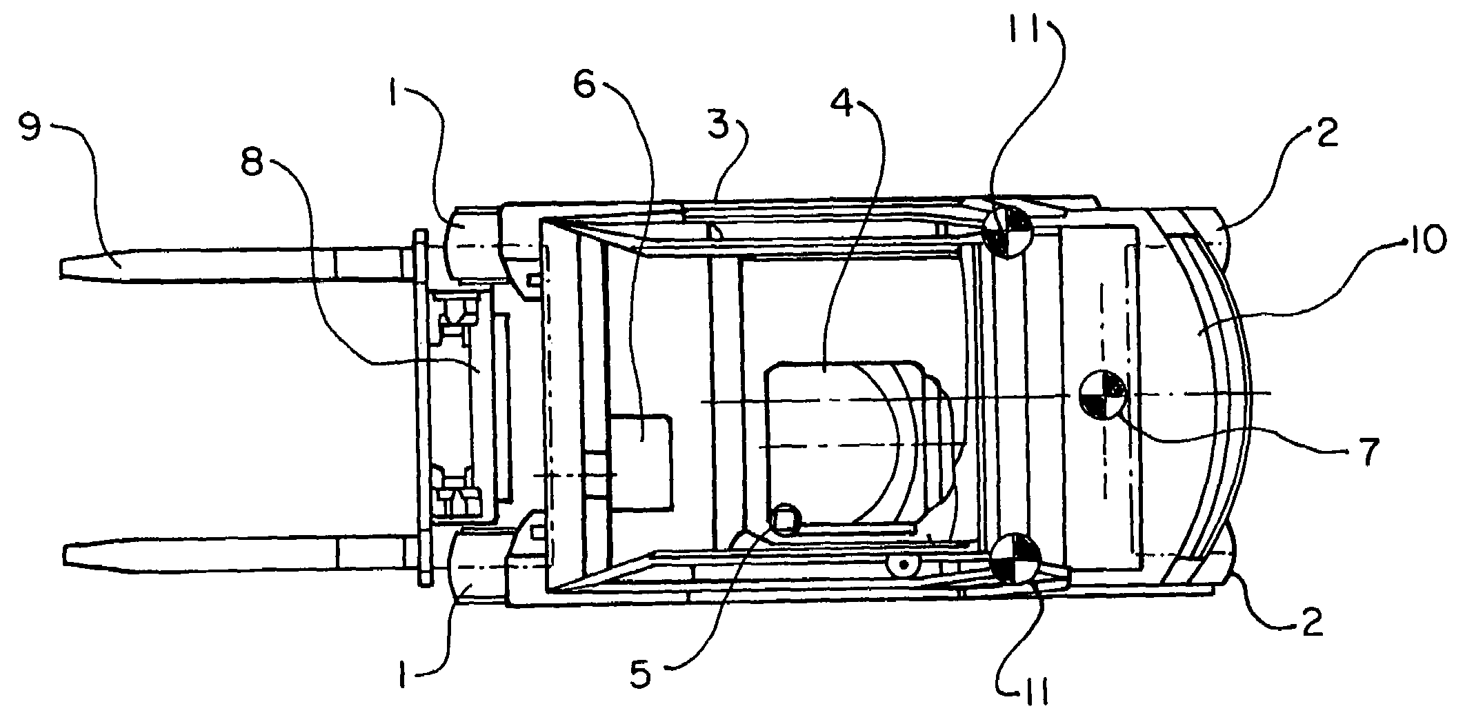
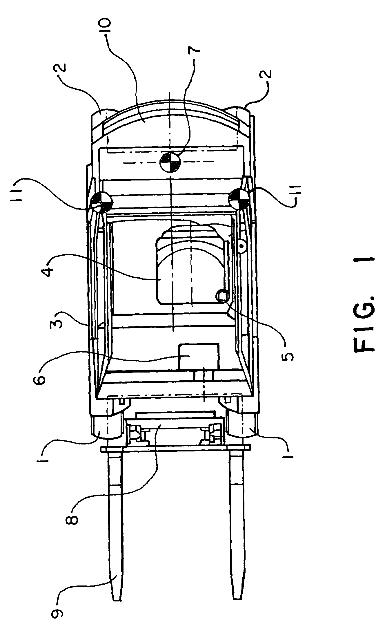
[0026]FIG. 1 shows an industrial truck according to the invention in the form of an overhead view of a fork lift truck. The industrial truck stands on the road or floor on two front wheels 1 and two steered rear wheels 2. In front of the front wheels 1, there are elevatable cargo holders 9 located on a lifting platform 8. A rear counterweight 10 is located in the vicinity of the rear wheels 2. Located in a driver's cab 3 of the industrial truck is a driver's seat 4 that faces forward and a steering wheel 5 that is located in front of the driver's seat 4. In the legroom of the driver's cab, there is also a screen 6 on which one of the images taken with different cameras is displayed as desired or as appropriate.

[0027]A first camera 7 is fastened to the upper side of the rear counterweight 10 and is provided to view the distant area behind the fork lift truck. The direction of view of the camera 7 can be fixed. It is also possible, however, to provide a swiveling device for the camera...


PUM


Abstract

An industrial truck, in particular a fork lift truck, has a driver's seat that is oriented in the forward direction, at least one screen that is located in the vicinity of the driver's seat, a first camera pointing toward the rear of the industrial truck and at least one additional camera that is directed toward the rear. The first camera is provided to view a distant area and the additional camera is provided to view a near area behind the industrial truck. The image taken with the first camera and / or the image taken with the additional camera can be displayed on the screen. There are advantageously two additional cameras to view the near area.

Description

BACKGROUND OF THE INVENTION[0001]1. Field of the Invention[0002]This invention relates to an industrial truck, such as a fork lift truck, having a driver's seat that is oriented in the forward-facing direction, at least one screen that is located in the vicinity of the driver's seat and a first camera that is directed toward the rear of the industrial truck. In particular, according to the invention at least one additional camera is provided, directed toward the rear, whereby the images taken with the cameras can be displayed on the screen.[0003]2. Brief Description of the Prior Art[0004]An industrial truck according to the prior art is described in German Patent No. 198 15 124 A1, for example.[0005]On industrial trucks of the type described, travel in reverse is made easier for the driver by the fact that the area behind the industrial truck is viewed by the camera and displayed on the screen. The driver thereby does not need to turn his head, an action that is necessary on convent...

Claims


Application Information

Patent Timeline
IPC IPC(8): H04N7/18G03B17/00B66F9/075B66F17/00
CPCB66F17/003B66F9/0755
Inventor RADEMACHER, FRANKBAVENDIEK, RAINERBUCHHOLZ, WOLFGANGARPING, FRANZ-JOSEFJANDKE, OLIVERARAND, PATRICK
Owner STILL GMBH
Learn More