
System, method, and software for relation-based product development

a relation-based product and system technology, applied in the field of product development techniques, can solve the problems of incomplete subassemblies that do not fully meet the expectations of that subassembly, engineers may have underperformed, specifications may not be fully realized, etc., and achieve the effect of reducing or eliminating at least some of the disadvantages and problems

Inactive Publication Date: 2009-12-01
TARGETED CONVERGENCE CORP
View PDF11 Cites 10 Cited by
  • Summary
  • Abstract
  • Description
  • Claims
  • Application Information

AI Technical Summary

Benefits of technology

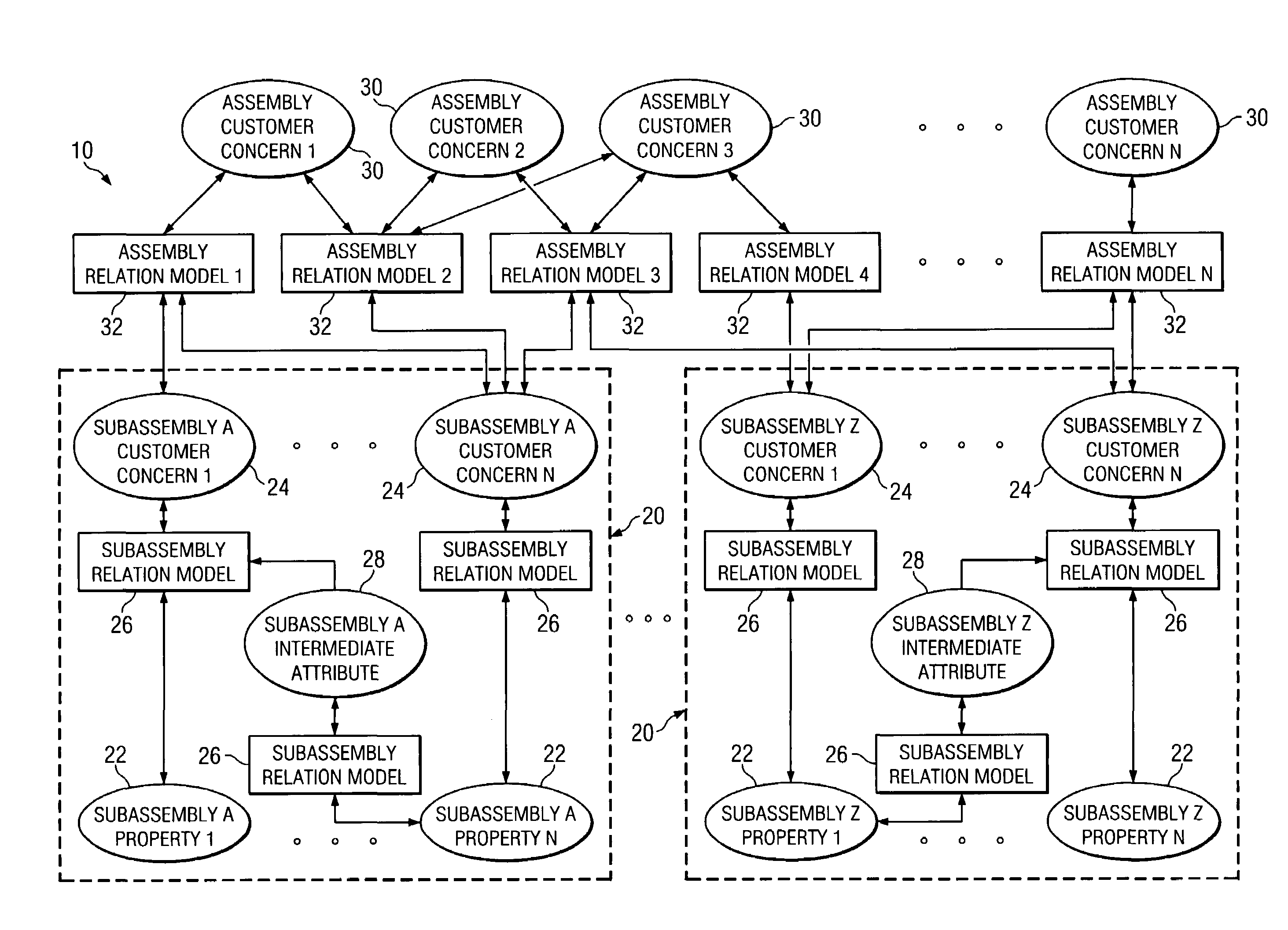
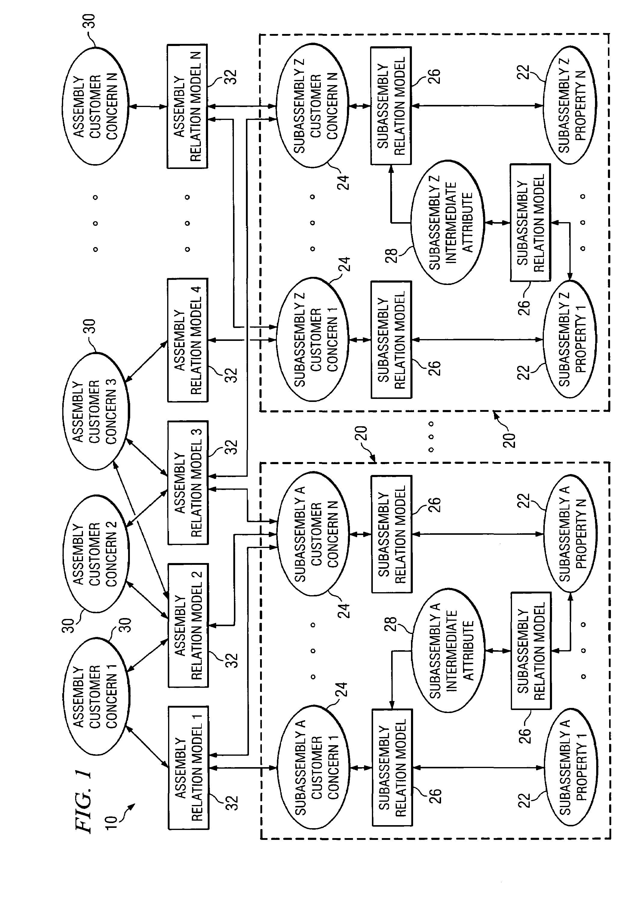
[0011]The present invention provides a system and method for relation-based product development that substantially eliminates or reduces at least some of the disadvantages and problems associated with previous systems and methods.

Problems solved by technology

The typical result of such a development process is that the completed subassemblies often do not fully meet the expectations for that subassembly.
The assembly engineers may have failed to embody all of their expectations in the subassembly specifications, the subassembly specifications may be interpreted differently by the subassembly engineers than by the assembly engineers, or the subassembly engineers may simply have not been able to develop a subassembly that would meet those specifications (for example, the specifications may have been unachievable or the engineers may have underperformed).
If the integration tests fail, as is often the case, then one or all subassembly development teams have to rework their designs to achieve revised or refined specifications.
Such looping can be very expensive to the overall development process and can make the process timing rather unpredictable.
When faced with assemblies that have several levels of hierarchy, the schedule delays become compounded and the costs can skyrocket.
Further, engineers end up spending massive amounts of time waiting due to other subassembly delays or re-working due to faulty specifications, which reduces overall productivity dramatically.
It is rarely put into a form that is even visible to other engineers; and in rare cases where it is documented, it is typically in a form that is not readily usable by other engineers.
Given how inefficiently the knowledge is captured and reused, such efforts would be considered wasteful.
Unfortunately, such failure to learn and such failure to make the learned knowledge usable results in a lack of flexibility and adaptability when problems occur (such as the integration test failures mentioned previously).
This often results in re-learning what has already been mostly learned, but not completely learned (or at least not in a way that makes the knowledge usable in the iteration).
The third dominant characteristic of typical product development efforts, which is a natural result of the first two characteristics, is the severe limitations on innovation during product development processes.
Despite the fact that most development efforts would like to encourage innovation, and despite the fact that many of these efforts require innovation in order to satisfy the goals, the vast majority of development efforts severely limit the amount of innovation that is possible.
First, the specification-based development process creates severe limitations on innovation, not allowing anything that would violate the specifications, while at the same time often requiring excessive innovation, in order to satisfy unachievable or near-unachievable specifications.
When you couple that with a process that does not encourage learning and does not make the knowledge that is learned readily available, many opportunities for innovation will not be available simply due to a lack of usable knowledge.
As a result, the vast majority of product development efforts deliver disappointing improvements over prior products.
That can dramatically reduce the competitiveness of the products.

Method used


Image

  • System, method, and software for relation-based product development
  • System, method, and software for relation-based product development
  • System, method, and software for relation-based product development

Examples


Embodiment Construction

[0028]As described above, typical product development techniques result in design decisions that limit that potential innovation, resulting in inferior product designs, and also typically requiring reworking of these inferior product designs, resulting in the product development being completed behind schedule. Productivity in product development is further limited by the great difficulty that design teams and businesses have in capturing the knowledge learned during previous product development projects in a form that can be used effectively on later projects. The knowledge that needs to be captured is not simply the prior design—it is the underlying knowledge that properly drove the design decisions embodied in those prior designs. A finished design specification, drawing, or solid model simply does not provide an understanding of this knowledge that drove the design decisions.

[0029]However, if a system that allows capture of and visibility to such product development knowledge is...


PUM


Abstract

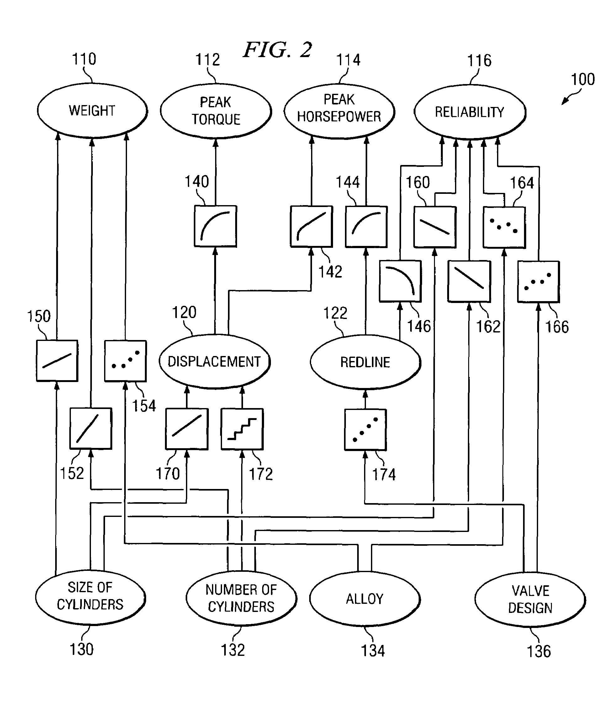
A product design method includes accessing a defined product design structure. The product design structure includes a number of customer concerns, a number of physical properties associated with components of the product, and a number of relation models. Each customer concern is associated with at least one physical property via at least one mathematical relationship defined in at least one of the relation models. The method also includes receiving a value associated with one or more of the physical properties and calculating (using one or more of the relation models) the effect of the received value associated with the one or more physical properties on one or more of the customer concerns. Furthermore, the method includes displaying the calculated effect on the one or more customer concerns and receiving one or more adjustments of the value associated with one or more of the physical properties to create a desired effect on one or more of the customer concerns.

Description

TECHNICAL FIELD[0001]The present invention relates generally to product development techniques and, more particularly, to a system, method, and software for relation-based product development.BACKGROUND OF THE INVENTION[0002]The vast majority of product development efforts share the same basic operational characteristics and yield similar levels of productivity. The first dominant characteristic is the way products are broken down into subassemblies. The assembly-level engineers define the subassemblies that will form the product / assembly. For each subassembly, the engineers create a set of design and build specifications that will allow that subassembly to work with the other subassemblies in such a way that they together will satisfy the specifications for the assembly as a whole. The subassembly engineers will then design their subassembly to conform to those specifications as best as possible. In doing so, the engineers may, in turn, define and specify further subassemblies (sub...

Claims


Application Information

Patent Timeline
Patent Type & Authority Patents(United States)
IPC IPC(8): G06F9/44
CPCG06F17/50G06F30/00
Inventor KENNEDY, BRIAN M.KENNEDY, MICHAEL N.
Owner TARGETED CONVERGENCE CORP
Learn More