LED assembly, and a process for manufacturing the LED assembly

a technology of led assembly and led diodes, which is applied in the direction of process and machine control, electric variable regulation, instruments, etc., can solve the problems of small input energy transfer, most of the input energy of traditional lighting is wasted, and the input energy of traditional lighting is transferred

Active Publication Date: 2009-12-01
DIALIGHT CORP
View PDF4 Cites 40 Cited by
  • Summary
  • Abstract
  • Description
  • Claims
  • Application Information

AI Technical Summary

Benefits of technology

[0021]Accordingly, one object of the present invention is to provide a novel LED assembly and novel method of manufacturing the LED assembly that can efficiently and consistently provide a desired color output of the LED assembly.
[0022]A more specific object of the present invention is to provide a novel LED assembly and novel method of manufacturing the LED assembly that can compensate for color variations of individual LEDs within the LED assembly.

Problems solved by technology

Although inexpensive to manufacture, the traditional incandescent bulb suffers from two disadvantages.
First, most of the input energy of traditional lighting is wasted as heat or infrared (non-visible) light; only a small amount of the input energy is transferred to visible light.
Second, the lifetime of the incandescent bulb is limited and when failure occurs it is catastrophic.
Halogen light sources are a slight improvement in efficiency and lifetime over incandescent light sources for a marginal increase in cost.
The filtering process takes white lighting and removes all the light except the required light of the specified color and therefore further reduces the efficiency of the light source.
Traditional lighting also is broadcast in all directions from the source, which may not be advantageous when the goal is to illuminate a small object.
Lastly, traditional lighting has a non-linear relationship between brightness and input current.
This non-linearity makes it difficult to dim the light source easily.
Generally, an individual LED produces a low level of light output that is insufficient for usage as a light source.
For architecture, the practical use of color remains limited largely due to the cumbersome use of theatrical grade fixtures in architectural applications.
Several LEDs are needed of each color, because a single LED does not provide sufficient light for a light engine.
Targeted output colors are difficult to achieve because of the manufacturing variations of the LEDs.
This has made the color stability of an array of RGB (Red, Green, Blue) LEDs difficult.
Lighting control systems or consoles address a limited number of light outputs with a limited number of possible color specifications and may require cumbersome hardware to address large lighting systems.
The current state of the art, however, does not resolve the following issues.
Exact color generation of a specified color is still not achievable.
Binning of the LEDs is not always sufficient to produce an accurate color across all environments because of the wide variations in the LED optical properties within a bin.

Method used


Image

  • LED assembly, and a process for manufacturing the LED assembly
  • LED assembly, and a process for manufacturing the LED assembly
  • LED assembly, and a process for manufacturing the LED assembly

Examples


first embodiment

[0060]the overall control operation of the LED assembly 100 of the present invention as shown in FIG. 6a is to utilize the stored baseline light output data of the Red LEDs, Green LEDs, and Blue LEDs that form the LED light 101 in conjunction with the stored environmental data, perform compensations based on the measured output of those lights and based on measured environmental values, and to output a desired light output.

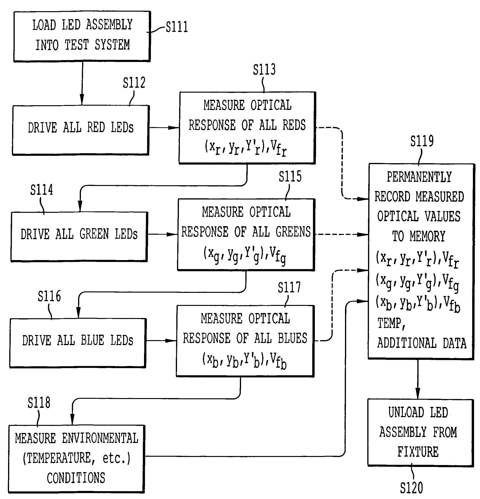
[0061]In the operation, stored values for the allRed response, allGreen response, and allBlue response are retrieved in processes 21-23. Those values correspond to the values stored in step S119 in FIG. 4. That retrieved information in processes 21-23 can be utilized by compensation and color mixing algorithms to allow a custom color generation to be realized.

[0062]More specifically, the retrieved stored values from processes 21-23 are provided to a process 24 that runs a compensation algorithm to predict an output under current environmental conditions based on t...

case 1

[0089]Iref is the driving current specified by the LED manufacturer and used in the manufacturing testing process to generate the stored values for processes 21, 22, and 23 of FIG. 6.[0090] If Ytotal′≧Yt′ then the following equations apply. The duty cycles are downscaled appropriately to account for the intensity.

case 2

[0091]Drt′=Yt′Ytotal′⁢DrtDgt′=Yt′Ytotal′⁢DgtDbt′=Yt′Ytotal′⁢DbtI=Itested[0092] If Ytotal′t′ then the following equations apply. The driving current is upscaled appropriately to accommodate the additional required brightness.

[0093]Drt′=DrtDgt′=DgtDbt′=DbtI=Yt′Ytotal′⁢Itested

[0094]The targeted color is therefore displayed for both case 1 and case 2 using the duty cycles (Drt′,Dgt′,Dbt′) and the driving current I.

[0095]FIG. 6b shows a modification of the embodiment of FIG. 6a, which can be applied to a device including different colored LEDs of Red LEDs, Blue LEDs, Green LEDs, and Amber LEDs. That is, instead of having a system with only three colors of Red, Blue, and Green, a system can incorporate four colors of Red, Blue, Green, and Amber. In those circumstances the operations shown in FIGS. 3a, 3b, and 4 will also perform operations directed to the Amber LEDs similarly as for the Red, Green, and Blue LEDs. As a result, measured optical values stored in memory will also include data...


PUM


Abstract

A manufacturing process for storing measured light output internal to an individual LED assembly, and an LED assembly realized by the process. The process utilizes a manufacturing test system to hold an LED light assembly a controlled distance and angle from the spectral output measurement tool. Spectral coordinates, forward voltage, and environmental measurements for the as manufactured assembly are measured for each base color LED. The measurements are recorded to a storage device internal to the LED assembly. Those stored measurements can then be utilized in usage of the LED assembly to provide accurate and precise control of the light output by the LED assembly.

Description

BACKGROUND OF THE INVENTION[0001]1. Field of the Invention[0002]The present invention is directed to an LED (light emitting diode) assembly and to a method of manufacturing the LED assembly, and which is particularly adapted to address issues of color differences between different LEDs within the LED assembly.[0003]2. Description of the Background Art[0004]Traditional light sources are most commonly either incandescent or gas discharge. Each has advantages and disadvantages. Although inexpensive to manufacture, the traditional incandescent bulb suffers from two disadvantages. First, most of the input energy of traditional lighting is wasted as heat or infrared (non-visible) light; only a small amount of the input energy is transferred to visible light. Second, the lifetime of the incandescent bulb is limited and when failure occurs it is catastrophic. Traditional fluorescent bulbs have a longer life, but have significant performance variations across a range of temperatures. At some...

Claims


Application Information

Patent Timeline
Patent Type & Authority Patents(United States)
IPC IPC(8): H05B37/02H05B44/00
CPCH05B33/0866H05B45/24
Inventor YOUNG, GARRETT
Owner DIALIGHT CORP
Why Eureka
Try Eureka