
Method and apparatus for using a virtual camera to dynamically refocus a digital image

a virtual camera and digital image technology, applied in image enhancement, image analysis, instruments, etc., can solve the problems of unrealistic looking, hard to produce convincing three-dimensional results without hard work, and artifacts often created during warping

Active Publication Date: 2009-11-24
ADOBE INC
View PDF11 Cites 139 Cited by
  • Summary
  • Abstract
  • Description
  • Claims
  • Application Information

AI Technical Summary

Problems solved by technology

However, existing blur filters only approximate the physics behind defocus and change of focus operations and as a result often produce unrealistic looking results.
However, artifacts are often created during the warping process due to a sparse or imperfect warping mesh.
Consequently, in practice it is hard to produce convincing three-dimensional results without hard work to establish a dense correspondence mesh of good quality.
Furthermore, artifacts are often created due to not being able to represent rays that fall between cameras (see A. Isaksen, L. McMillan and S. Gortler, “Dynamic Reparameterized Light Fields,” Proceedings of SIGGRAPH 2000.)

Method used


Image

  • Method and apparatus for using a virtual camera to dynamically refocus a digital image
  • Method and apparatus for using a virtual camera to dynamically refocus a digital image
  • Method and apparatus for using a virtual camera to dynamically refocus a digital image

Examples


Embodiment Construction

[0020]The following description is presented to enable any person skilled in the art to make and use the invention, and is provided in the context of a particular application and its requirements. Various modifications to the disclosed embodiments will be readily apparent to those skilled in the art, and the general principles defined herein may be applied to other embodiments and applications without departing from the spirit and scope of the present invention. Thus, the present invention is not limited to the embodiments shown, but is to be accorded the widest scope consistent with the principles and features disclosed herein.

[0021]The data structures and code described in this detailed description are typically stored on a computer-readable storage medium, which may be any device or medium that can store code and / or data for use by a computer system. This includes, but is not limited to, magnetic and optical storage devices, such as disk drives, magnetic tape, CDs (compact discs)...


PUM


Abstract

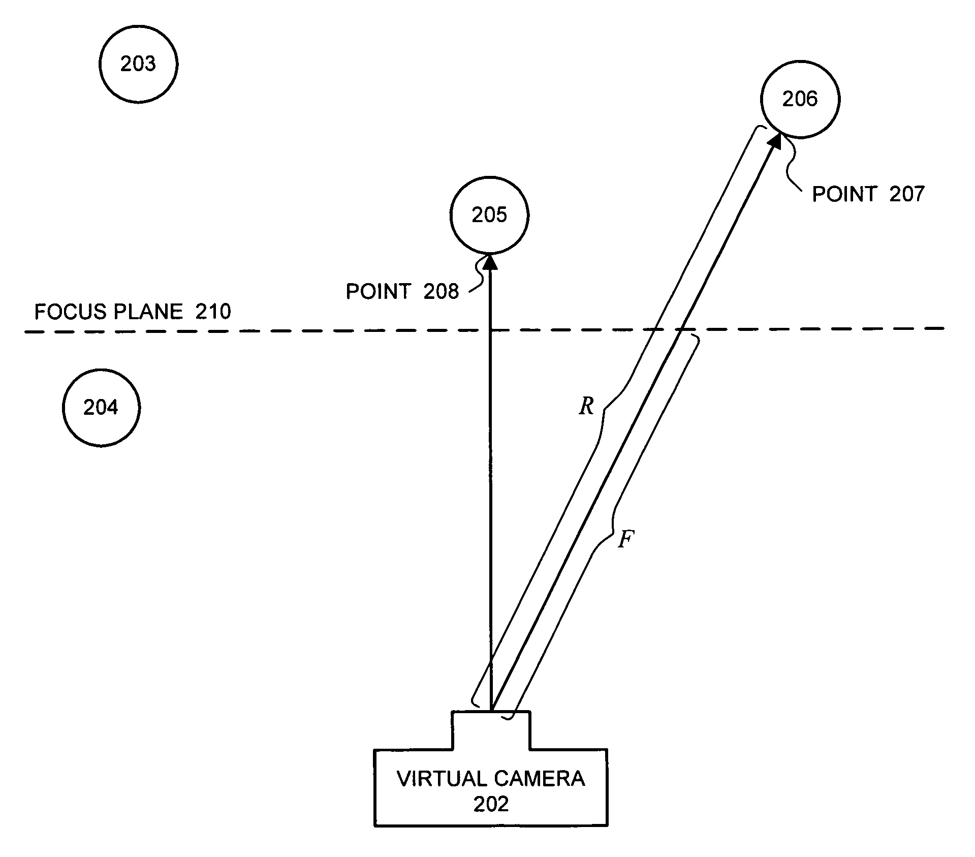
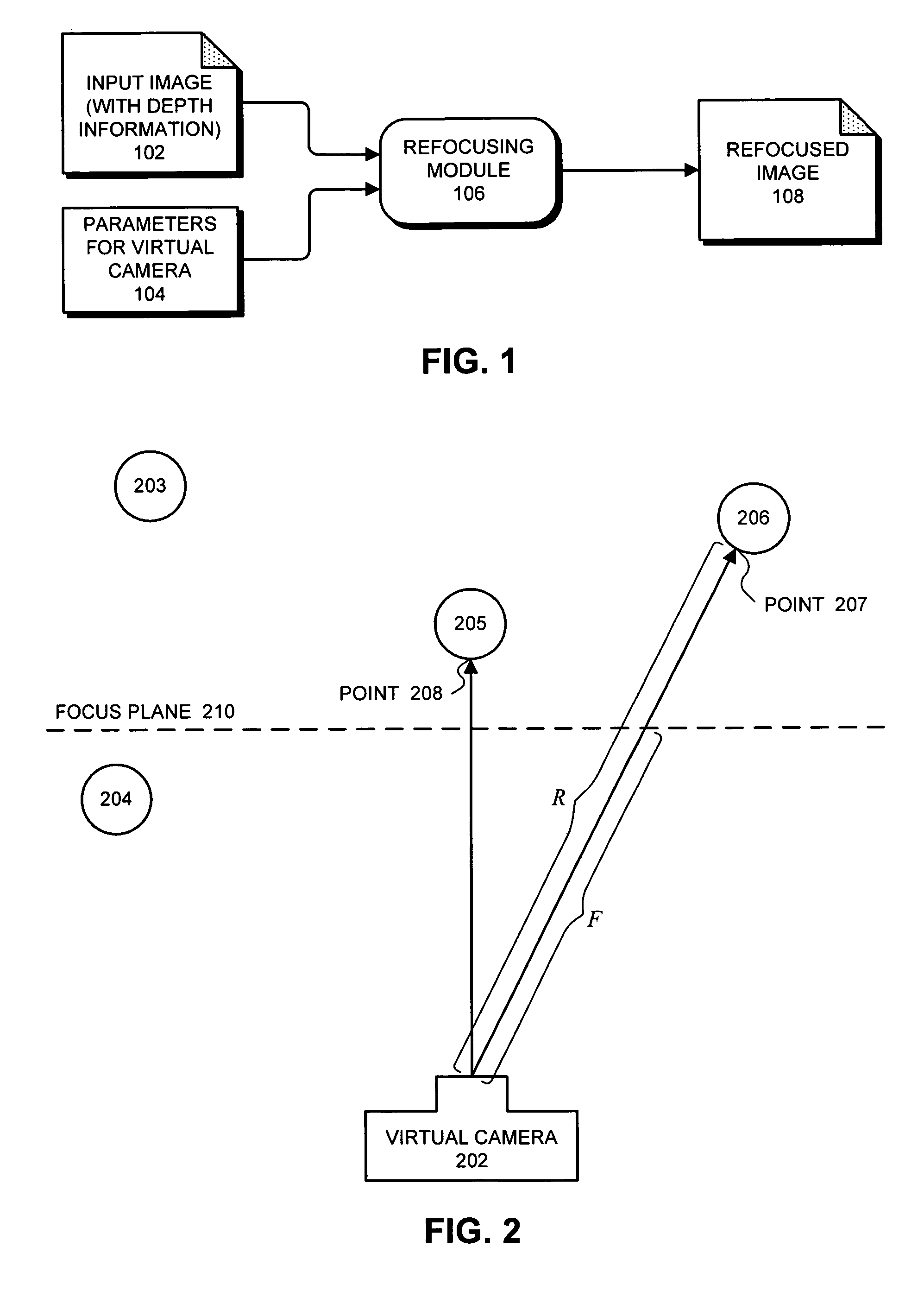
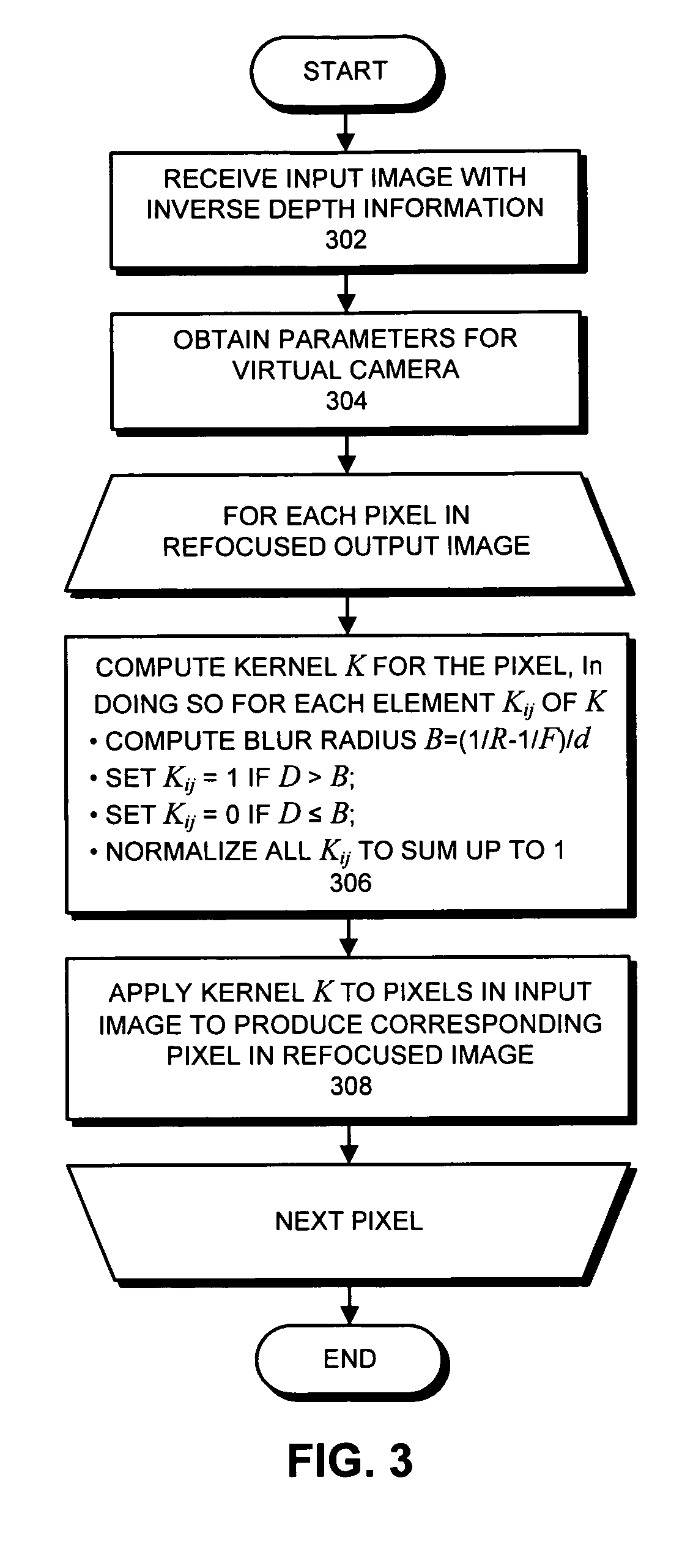
One embodiment of the present invention provides a system that dynamically refocuses an image to simulate a focus plane and a depth-of-field of a virtual camera. During operation, the system receives an input image, wherein the input image includes depth information for pixels in the input image. The system also obtains parameters that specify the depth-of-field d and the location of the focus plane for the virtual camera. Next, the system uses the depth information and the parameters for the virtual camera to refocus the image. During this process, for each pixel in the input image, the system uses the depth information and the parameters for the virtual camera to determine a blur radius B for the pixel. The system then uses the blur radius B for the pixel to determine whether the pixel contributes to neighboring pixels in the refocused image.

Description

BACKGROUND[0001]1. Field of the Invention[0002]The present invention relates to computer-based tools for manipulating digital images. More specifically, the present invention relates to a method and an apparatus for dynamically refocusing a digital image to simulate changing the focus plane and the depth-of-field of a “virtual camera.”[0003]2. Related Art[0004]Dramatic increases in computational power in recent years make it possible to perform a wide range of sophisticated computational operations on digital images. In particular, there are presently a number of techniques for using three-dimensional information to produce images that create a feeling of three-dimensional depth.[0005]Blur filters are sometimes used to selectively defocus an image (or parts of an image) to simulate defocus and change of focus, thereby creating a feeling of three-dimensionality. However, existing blur filters only approximate the physics behind defocus and change of focus operations and as a result o...

Claims


Application Information

Patent Timeline
IPC IPC(8): G06K9/40
CPCG06T5/003H04N13/0022G06T2207/10012G06T2207/10028H04N2213/003H04N2213/006H04N13/128G06T5/73
Inventor GEORGIEV, TODOR G.
Owner ADOBE INC
Learn More