Ratchet cap for winch

a technology of ratchets and ratchets, which is applied in the field of ratchets, can solve the problems of significant slowdown of operation, and achieve the effect of lessening the tension of the strap

Inactive Publication Date: 2009-11-17
ANCRA INTERNATIONAL CORPORATON
View PDF7 Cites 19 Cited by
  • Summary
  • Abstract
  • Description
  • Claims
  • Application Information

AI Technical Summary

Benefits of technology

[0004]The device of the present invention employs a ratcheting cap which is attached to the drive shaft of the winch. Such attachment can be made to prior art winches without any modification thereto and enables driving of the drive shaft without the need to remove the drive lever from an aperture in which is installed and reinstalling it in another aperture. The ratcheting cap has a first section which is securely installed on the drive shaft. A second section of the cap has a pair of oppositely positioned spring urged pin members having rounded end portions. These end portions fit into recesses formed in an opposing plate in the first cap section. There are a plurality of such recesses which run all around the plate. One end of each recess runs substantially at right angles to the surface of the plate so as to prevent the rounded end portions of the pins from moving out of a recess when driven against this end. The other end of each recess has a slanted configuration relative to the surface of the ratchet plate so as to permit the rounded end portions of the pins to run out of their associated recess into the adjoining recess when the ratcheting cap is turned manually. The drive for the winch thus can be moved backwardly without lessening the tension on the strap when it reaches a down position against the deck, thereby permitting additional tightening of the strap around the winch without removing the drive lever.

Problems solved by technology

This slows down the operation significantly, particularly where there are a large number of winches to be tightened down.

Method used


Image

  • Ratchet cap for winch
  • Ratchet cap for winch
  • Ratchet cap for winch

Examples


Embodiment Construction

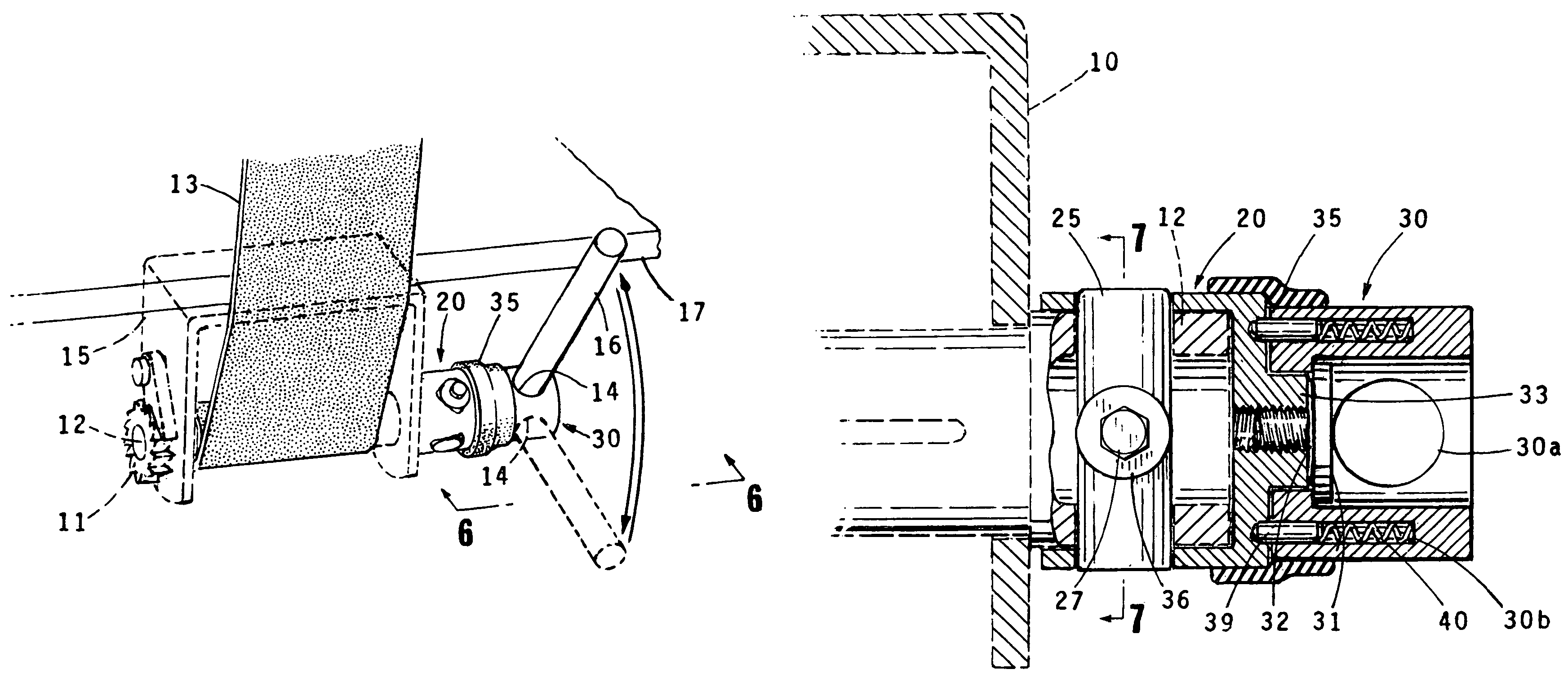
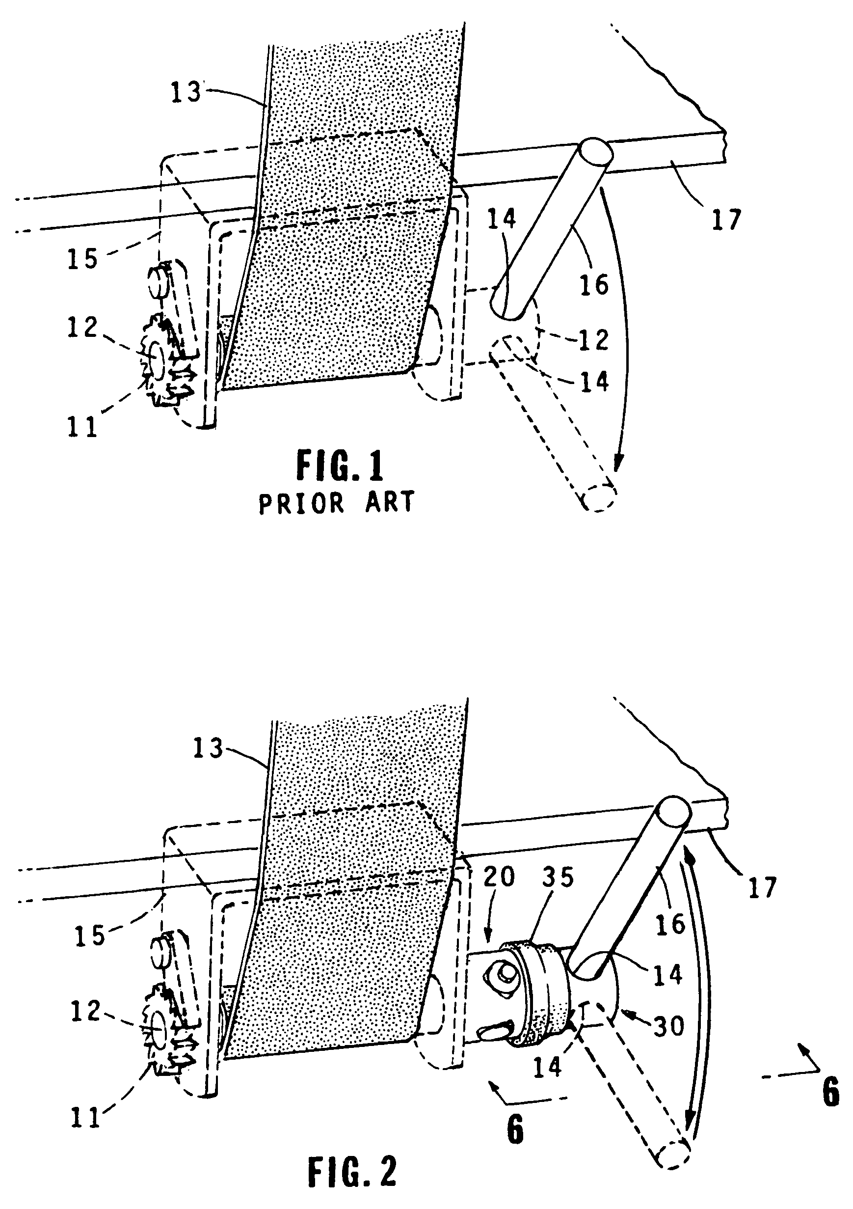
[0014]Referring to FIG. 2, a first section 20 of the ratcheting cap is fixedly attached to the drive shaft 12. A second ratcheting cap section 30 is connected to first cap section 20 for rotatable motion relative thereto in one direction but not in the opposite direction. Thus, the second cap section can be rotatably moved backward away from the floor to permit the lever arm 16 to be drawn upwardly away from the floor, as shown in FIG. 2. This does not release the ratchet 11 but raises the lever arm so that it can then be driven downwardly to tighten the ratchet and along with it strap 13.

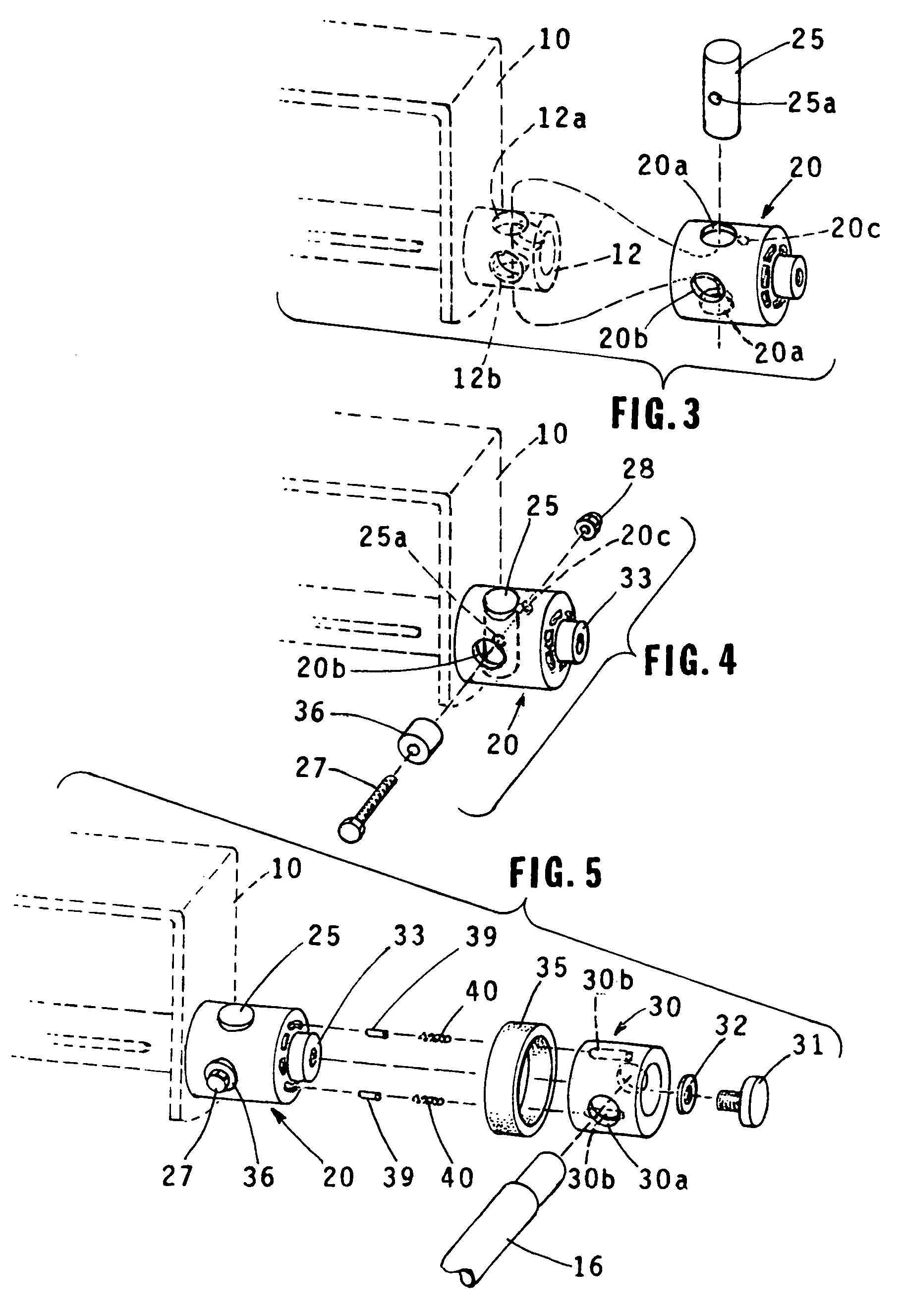
[0015]Referring now to FIGS. 3-7, the shaft 12 of the winch 10 has two first pairs of opposing apertures 12a and 12b formed at right angles to each other in the opposing walls thereof. The ratcheting cap section 20 has two pairs of opposing apertures 20a and 20b formed therethrough. The cap section 20 is removably attached to the shaft 12 of the winch by a post 25 which is fitted through apertures ...


PUM

PropertyMeasurementUnit
anglesaaaaaaaaaa
rotational movementaaaaaaaaaa
movementaaaaaaaaaa

Abstract

A winch used for tightening a strap to retain an article, which may be cargo, on the deck of a vehicle has a ratcheting mechanism which tightens the strap around a cylindrical shaft. A ratchet cap installed on the winch has two sections. One of these sections is fixedly attached to the winch drive shaft This first section has a plurality of spaced recesses running around a surface plate thereof. Spring urged pins with rounded end surfaces are mounted in receptacles formed in the second cap section. The rounded ends of the spring urged pins are urged against the surfaces of the recesses. The pins are prevented from moving out of the recesses in one direction by a right angled end portion of the recess in this one direction and are free to move out of a recess over a slanted recess end portion into an adjoining recess in the opposite direction. At least one aperture is formed in the cap into which a lever for driving the winch is fitted. When the lever hits against the deck and cannot be moved any further, the ratchet cap can be rotated in its free moving direction to enable further driving of the winch downwardly to tighten the strap.

Description

BACKGROUND OF THE INVENTION[0001]This invention relates to a ratchet cap for installation on a winch used for securing a strap which retains an article on a floor (typically the floor of a vehicle). The ratchet cap enables driving of the winch with a lever in a single position relative to the winch without the need for removing the lever and placing it in another drive position when it reaches the limit of its rotation.Description of the Related Art[0002]A typical prior art winch for securing a strap which retains an article, which may be cargo, on the deck of a vehicle is illustrated in FIG. 1. This prior art winch has a ratchet wheel 11 which is driven in one direction by drive shaft 12 which tightens strap 13 around the shaft. The ratchet wheel 11 only permits rotational movement in the tightening direction and prevents movement in the opposite direction unless manually released.[0003]The drive shaft 12 of this prior art device has apertures 14 formed therein, ninety degree from ...

Claims


Application Information

Patent Timeline
Patent Type & Authority Patents(United States)
IPC IPC(8): B21F9/00
CPCB60P7/083Y10T24/2121
Inventor LEONE, THOMAS H.KNOX, HOWARD THOMAS
Owner ANCRA INTERNATIONAL CORPORATON
Why Eureka
Try Eureka