Vehicular window regulator
a technology for window regulators and vehicle windows, which is applied in the direction of door/window fittings, wing accessories, transportation and packaging, etc., can solve the problems of increasing friction, and affecting the smooth vertical motion, so as to achieve smooth vertical motion and simple structure
- Summary
- Abstract
- Description
- Claims
- Application Information
AI Technical Summary
Benefits of technology
Problems solved by technology
Method used
Image
Examples
first embodiment
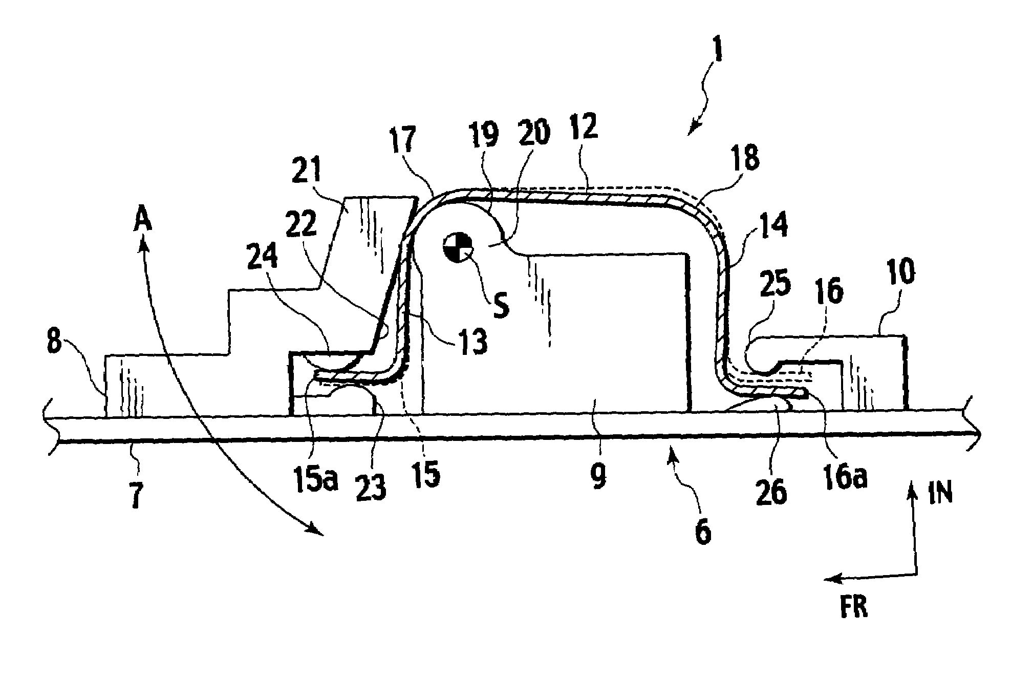
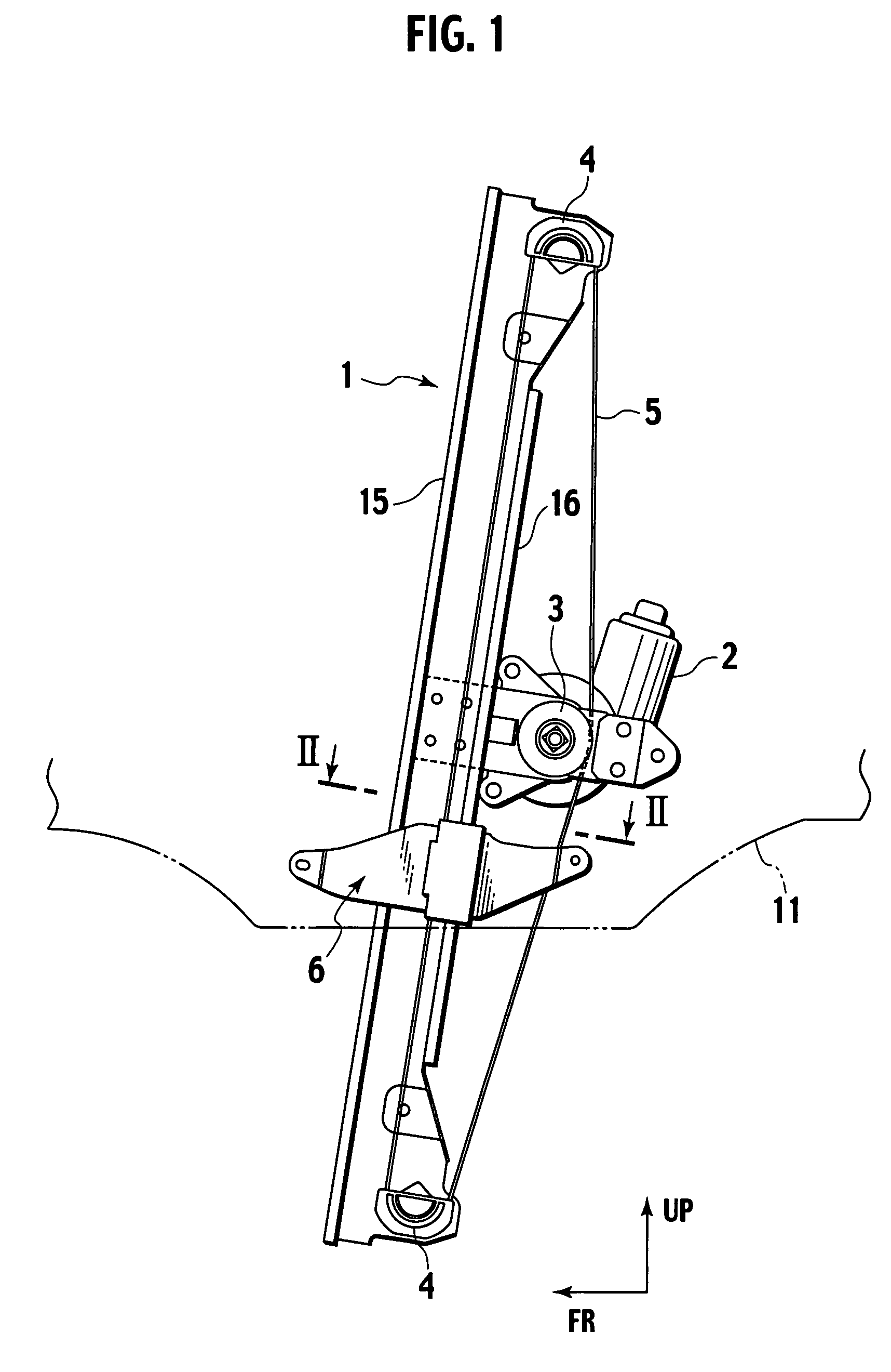
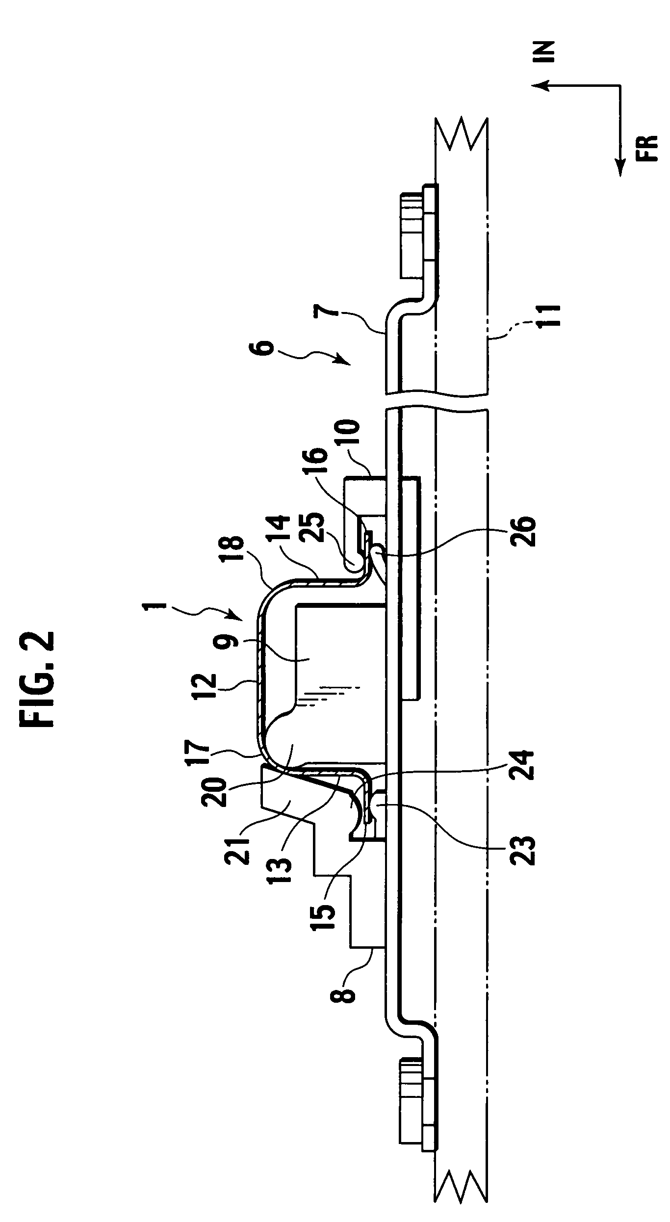
[0028]FIG. 1 is a side view of a window regulator according to a first embodiment of the present invention, provided on a left door as viewed from outside of a vehicle. FIG. 2 is a sectional view (of only a guide rail) of the window regulator taken along the arrow line II-II in FIG. 1. FIG. 3 is an exploded perspective view showing an inscribed projection and a circumscribed projection. FIG. 4 is a sectional view of relevant parts of the window regulator. FIG. 5 is a sectional view of relevant parts corresponding to FIG. 4 showing a state where the carrier plate rotates. FIG. 6 is an enlarged sectional view showing a state where the inscribed projection and the circumscribed projection sandwich a curved portion. FIG. 7 is an enlarged sectional view corresponding to FIG. 6 showing a state where the carrier plate rotates. In FIG. 7, a turning motion of the carrier plate is exaggerated so that operation can be understood easily. In the drawings, FR represents vehicle front in the longi...
second embodiment
[0048]FIG. 8 is a sectional view of relevant parts of a window regulator according to a second embodiment of the present invention. The window regulator of the second embodiment has like constituent elements as those of the first embodiment. Therefore, these like constituent elements are designated with like reference symbols and redundant explanations will be omitted.
[0049]In the present embodiment, the flanges 28 and 29 in front of and behind a guide rail 27 are curved into arcs around the curving center S of an inscribed projection 30.
[0050]Like the first embodiment, a carrier plate 31 has three protrusions 32, 33 and 34, the central protrusion 33 is provided with the inscribed projection 30, and the inscribed projection 30 is formed with a curved surface 35 which is inscribed with the curved portion 17. In the present embodiment, the projections 32, 33 and 34 and a sandwiching piece 37 correspond to the elements to be guided.
[0051]The rear flange 29 is formed by bending a rear w...
third embodiment
[0055]FIG. 9 is a sectional view of relevant parts of a window regulator according to a third embodiment of the present invention. The window regulator of the third embodiment has like constituent elements as those of the first or second embodiment. Therefore, these like constituent elements are designated with like reference symbols and redundant explanations will be omitted.
[0056]In the present embodiment, a curved portion 48 is formed on a corner portion of a boundary between a front wall 44 of the guide rail 43 and a front flange 45.
[0057]A carrier plate 49 has three protrusions 50, 51 and 52. The front protrusion 50 is provided with an inscribed projection 56, and the inscribed projection 56 is formed with a curved surface 55 which is inscribed with the curved portion 48. In the present embodiment, the protrusions 50, 51 and 52 and the sandwiching piece 54 correspond to the elements to be guided.
[0058]The rear flange 47 formed by bending the rear wall 46 of the guide rail 43 is...
PUM
 Abstract
Description
Claims
Application Information
 - R&D
- Intellectual Property
- Life Sciences
- Materials
- Tech Scout
- Unparalleled Data Quality
- Higher Quality Content
- 60% Fewer Hallucinations
Browse by: Latest US Patents, China's latest patents, Technical Efficacy Thesaurus, Application Domain, Technology Topic, Popular Technical Reports.
© 2025 PatSnap. All rights reserved.Legal|Privacy policy|Modern Slavery Act Transparency Statement|Sitemap|About US| Contact US: help@patsnap.com


