
Patient lifting device

a lifting device and patient technology, applied in the field of patients' lifting devices, can solve the problems of requiring a large amount of air to inflate, discomforting and embarrassing methods of placing a bedpan beneath the patient, and a very painful experience of manual lifting of the hips

Inactive Publication Date: 2009-11-17
FAIOLA NORMAN A
View PDF7 Cites 9 Cited by
  • Summary
  • Abstract
  • Description
  • Claims
  • Application Information

AI Technical Summary

Benefits of technology

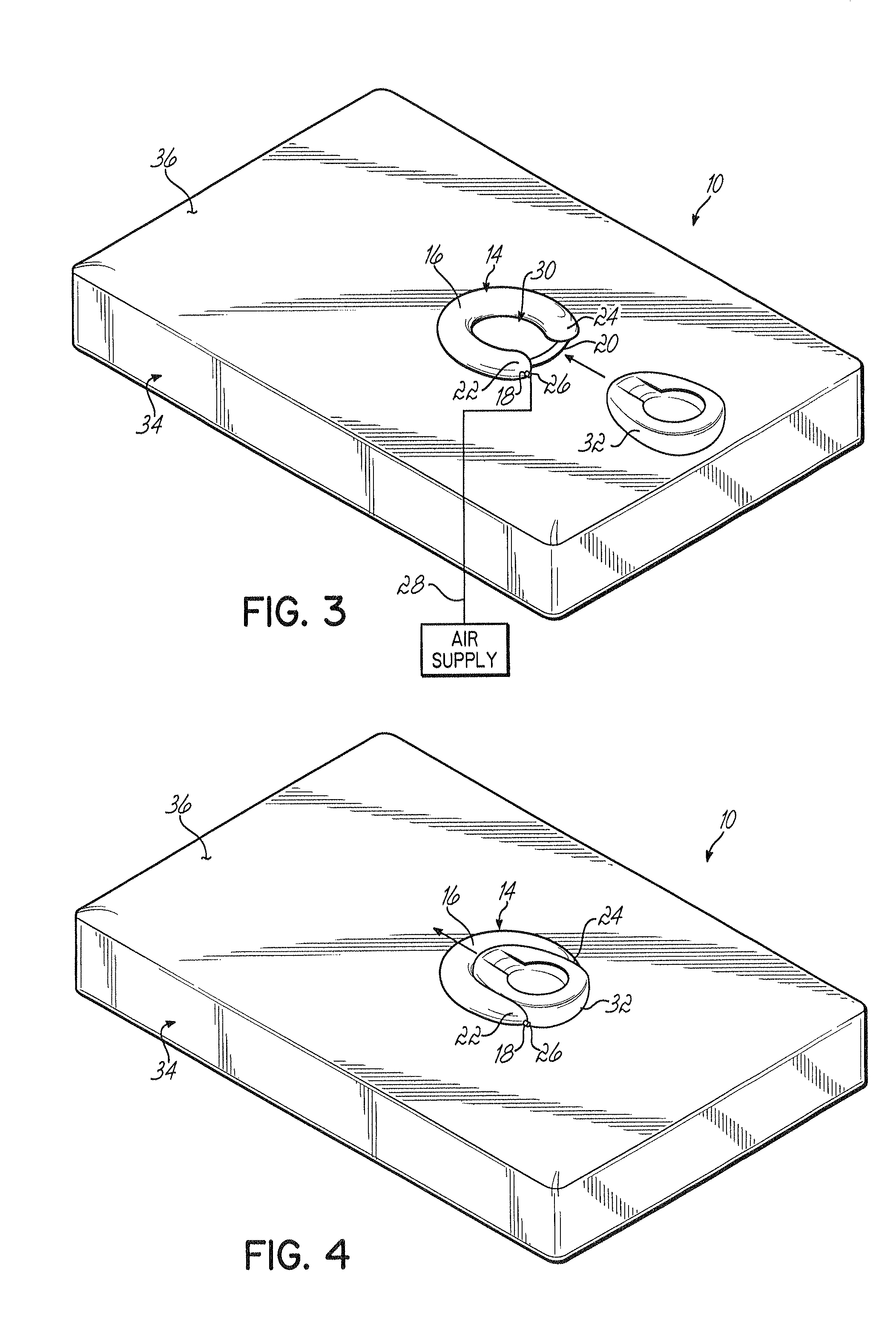
[0006]A method for placing a bedpan under a patient on a mattress is also disclosed, where the mattress has a patient lift device including an inflatable U-shaped bladder, an air port in the bladder, and an air supply line attached to the air port. The method includes delivering air through the air supply line to inflate the bladder and lift the patient, sliding a standard bedpan under the patient's raised rectal area, and moving the bedpan into the middle of the bl

Problems solved by technology

For most patients with spinal injuries who need to stay horizontal or stationary for treatment reasons, the manual lifting of the hips can be a very painful experience.
Even for patients allowed to move on the bed, these methods of placing a bedpan beneath the patient can be discomforting and embarrassing.
While each of these prior art devices addresses the problem of moving patients, the Stefano device requires a large amount of air to inflate and adds essentially another entire mattress to hospital beds and adds further difficulty in placing and removing the device.
The Martin device can be inconvenient in situations where nothing should be attached directly to the patient in the belt area, and that device also still needs to be initially placed under a patient by lifting his hips.

Method used


Image

  • Patient lifting device
  • Patient lifting device
  • Patient lifting device

Examples


Embodiment Construction

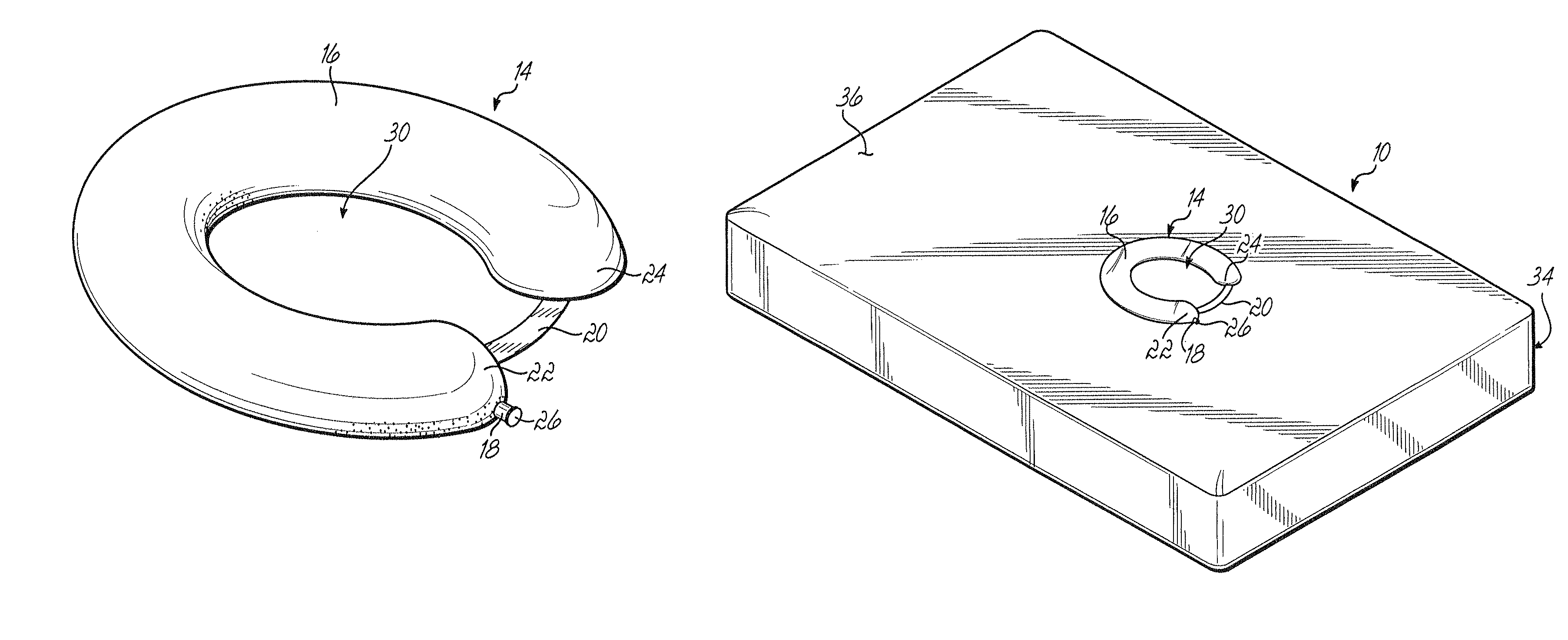
[0016]One embodiment of an assembly 10 and associated method for supporting a patient 12 including a patient lifting device 14 is shown in FIGS. 1-5B. The patient lifting device 14 comprises an inflatable U-shaped bladder 16 adapted to lift the rectal area of a supine patient 12. The bladder 16 may be made of any material suited for inflation such as rubber. The patient lifting device 14 also includes an air port 18 in the bladder 16 for inflating and deflating the bladder 16, and a tether 20 coupled near the terminal ends 22, 24 of the U-shaped bladder 16 to maintain the U-shape of the bladder 16. The air port 18 is shown in FIGS. 1-5B located near the terminal end 22 of the bladder 16, but one skilled in the art will appreciate that the air port 18 may be located anywhere convenient on the bladder.

[0017]The air port 18 includes a nozzle 26 for connecting the air port 18 to an air supply line 28. The air supply line 28 delivers air through the air port 18 to inflate the bladder 16 ...


PUM


Abstract

An inflatable lifting device is disclosed for lifting the rectal area of a patient laying on a mattress. The inflatable lifting device is an inflatable U-shaped bladder with an air port to supply air into the bladder and a tether to maintain the U-shape of the bladder. The inflated bladder creates a cavity sized for the easy insertion and removal of a bedpan under the patient. The inflatable lifting device may be positioned on top of an upper surface of the mattress or within the mattress just below the upper surface.

Description

FIELD OF THE INVENTION[0001]This invention relates to a lifting device for patients who are in bed, and more particularly to a lifting device that lifts a patient adjacent to the base of his spine and enables the easy insertion and removal of a bedpan under the patient.BACKGROUND[0002]The use of bedpans for hospital patients who are reclined in a bed is well-known, and many types of bedpans have been developed to allow for easier use and movement. The traditional methods of placing a bedpan underneath a patient include manually lifting the hips of a patient or turning a patient on his side before sliding the bedpan in place. For most patients with spinal injuries who need to stay horizontal or stationary for treatment reasons, the manual lifting of the hips can be a very painful experience. Even for patients allowed to move on the bed, these methods of placing a bedpan beneath the patient can be discomforting and embarrassing. Consequently, there is a need for an alternative method ...

Claims


Application Information

Patent Timeline
IPC IPC(8): A61G7/02
CPCA61G7/1021A61G7/1009
Inventor FAIOLA, NORMAN A.
Owner FAIOLA NORMAN A
Learn More