
Allocating channels in a mobile ad hoc network

a mobile ad hoc network and channel allocation technology, applied in the field of communication networks, can solve the problems of limited communication and computation capabilities, limited bandwidth of the system, and serious challenges of mobile ad hoc networks, and achieve the effect of efficient use of a plurality

Active Publication Date: 2009-11-10
STINGRAY IP SOLUTIONS LLC
View PDF19 Cites 29 Cited by
  • Summary
  • Abstract
  • Description
  • Claims
  • Application Information

AI Technical Summary

Benefits of technology

[0012]In view of the foregoing background, it is therefore an object of the present invention to provide dynamic channel allocation in a mobile ad hoc network to efficiently make use of a plurality of channels.

Problems solved by technology

Mobile ad hoc networks pose serious challenges to the designers.
Due to the lack of a fixed infrastructure, nodes must self-organize and reconfigure as they move, join or leave the network.
Nodes are often powered by batteries and have limited communication and computation capabilities.
The bandwidth of the system is usually limited.
Because the network topology changes arbitrarily as the nodes move, information is subject to becoming obsolete, and different nodes often have different views of the network, both in time (information may be outdated at some nodes but current at others) and in space (a node may only know the network topology in its neighborhood and not far away from itself).
A routing protocol needs to adapt to frequent topology changes and with less accurate information.
Gathering fresh information about the entire network is often costly and impractical.
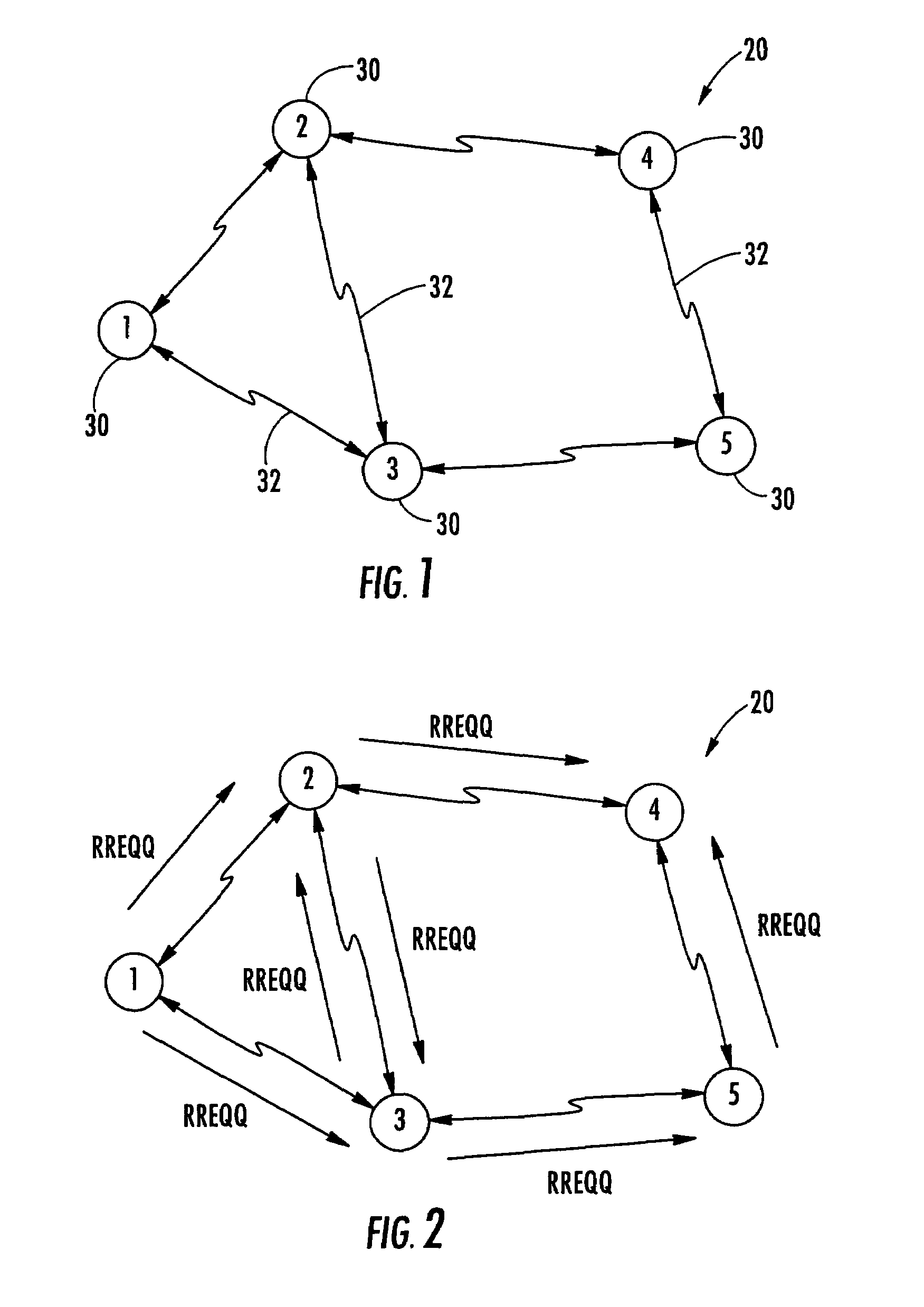
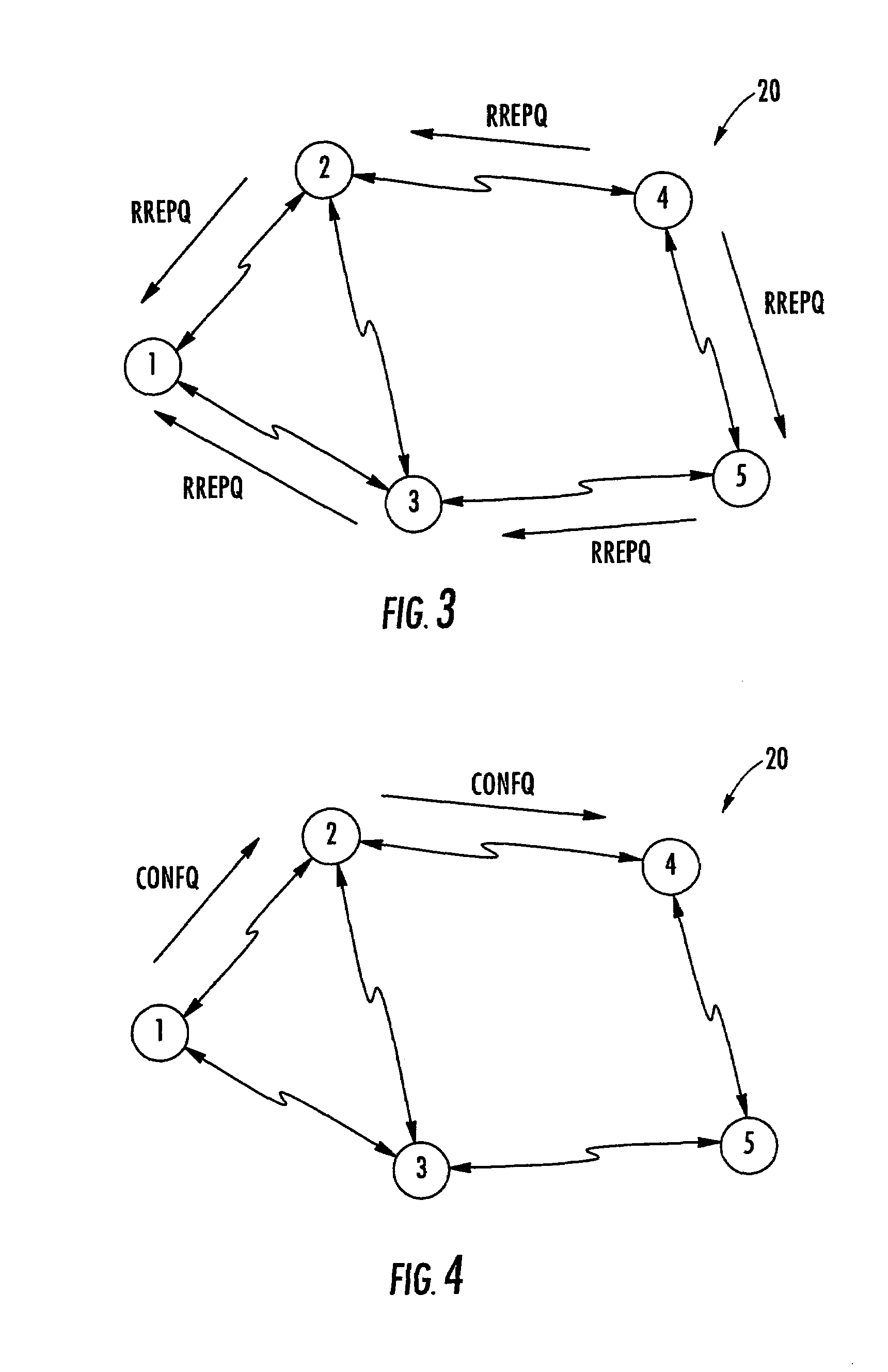
Many routing protocols are reactive (on-demand) protocols: they collect routing information only when necessary and to destinations they need routes to, and do not maintain unused routes.
Because of the limited, shared bandwidth of the network, and lack of central controller which can account for and control these limited resources, nodes must negotiate with each other to manage the resources required for QoS routes.
This is further complicated by frequent topology changes.
Due to these constraints, QoS routing is more demanding than best-effort routing.

Method used


Image

  • Allocating channels in a mobile ad hoc network
  • Allocating channels in a mobile ad hoc network
  • Allocating channels in a mobile ad hoc network

Examples


Embodiment Construction

[0029]The present invention will now be described more fully hereinafter with reference to the accompanying drawings, in which preferred embodiments of the invention are shown. This invention may, however, be embodied in many different forms and should not be construed as limited to the embodiments set forth herein. Rather, these embodiments are provided so that this disclosure will be thorough and complete, and will fully convey the scope of the invention to those skilled in the art. Like numbers refer to like elements throughout, and prime notation is used to indicate similar elements in alternative embodiments.

[0030]As will be appreciated by those skilled in the art, portions of the present invention may be embodied as a method, data processing system, or computer program product. Accordingly, these portions of the present invention may take the form of an entirely hardware embodiment, an entirely software embodiment, or an embodiment combining software and hardware aspects. Furt...


PUM


Abstract

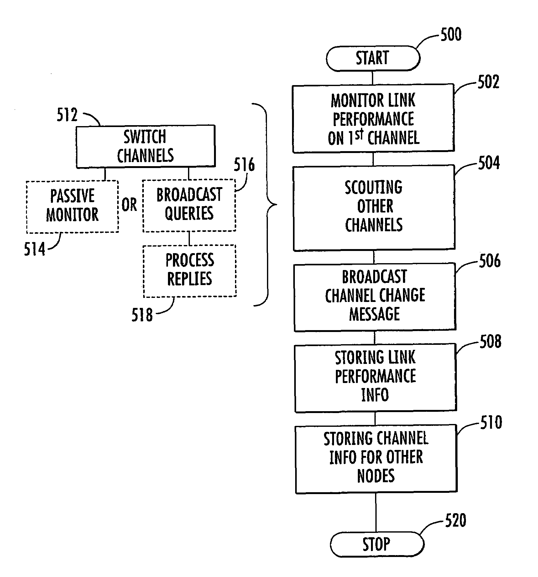
A mobile ad hoc network includes a plurality of wireless mobile nodes and a plurality of wireless communication links connecting the plurality of nodes together over a plurality of channels. The method includes each node monitoring link performance on a first channel, link performance being based upon at least one quality of service (QoS) threshold, and each node scouting one or more other available channels when the monitored link performance on the first channel falls below the QoS threshold. The QoS threshold is preferably based upon at least one of available bandwidth, error rate, end-to-end delay, end-to-end delay variation, hop count, expected path durability, and priority.

Description

FIELD OF THE INVENTION[0001]The present invention relates to the field of communication networks, and, more particularly, to mobile ad hoc wireless networks and related methods.BACKGROUND OF THE INVENTION[0002]Wireless networks have experienced increased development in the past decade. One of the most rapidly developing areas is mobile ad hoc networks. Physically, a mobile ad hoc network includes a number of geographically-distributed, potentially mobile nodes sharing a common radio channel. Compared with other type of networks, such as cellular networks or satellite networks, the most distinctive feature of mobile ad hoc networks is the lack of any fixed infrastructure. The network is formed of mobile nodes only, and a network is created on the fly as the nodes transmit with each other. The network does not depend on a particular node and dynamically adjusts as some nodes join or others leave the network.[0003]In a hostile environment where a fixed communication infrastructure is u...

Claims


Application Information

Patent Timeline
IPC IPC(8): H04W72/00H04W4/00H04L12/28H04B7/26H04L12/56H04W40/02H04W40/28H04W84/18
CPCH04W40/02H04L45/302H04L45/26H04W40/28H04W72/04H04W84/18H04W24/00H04W28/04
Inventor BILLHARTZ, TOM
Owner STINGRAY IP SOLUTIONS LLC
Learn More