
Residual wound quantity display mechanism of timepiece and timepiece with residual wound quantity display mechanism

a display mechanism and timepiece technology, applied in the field of timepiece with residual wound quantity display mechanism, can solve the problems of inability to display in a straight line, user who can only see an external appearance to feel a change,

Inactive Publication Date: 2009-11-10
SEIKO INSTR INC
View PDF7 Cites 8 Cited by
  • Summary
  • Abstract
  • Description
  • Claims
  • Application Information

AI Technical Summary

Benefits of technology

[0009]It is an aspect of the present invention to provide a residual wound quantity display mechanism of a timepiece, in which it is possible to change a way of the display without changing a basic structure, and a timepiece with the mechanism concerned.

Problems solved by technology

By this, although a display region can be selected, a display itself is not different from a conventional arc-like or fan-shaped display and, from the fact that a center of the arc or fan in the display concerned exists in a range of a spread of the timepiece, it is difficult to cause a user who can see only an external appearance to feel a change (idea).
Although JP-A-2006-234432 is one having a novelty in the display in a point that there is performed a display like a straight line, it is one in which a male thread and a female thread are combined for the display like the straight line, so that a display in a form other than the straight line is actually impossible.

Method used


Image

  • Residual wound quantity display mechanism of timepiece and timepiece with residual wound quantity display mechanism
  • Residual wound quantity display mechanism of timepiece and timepiece with residual wound quantity display mechanism
  • Residual wound quantity display mechanism of timepiece and timepiece with residual wound quantity display mechanism

Examples


embodiment 1

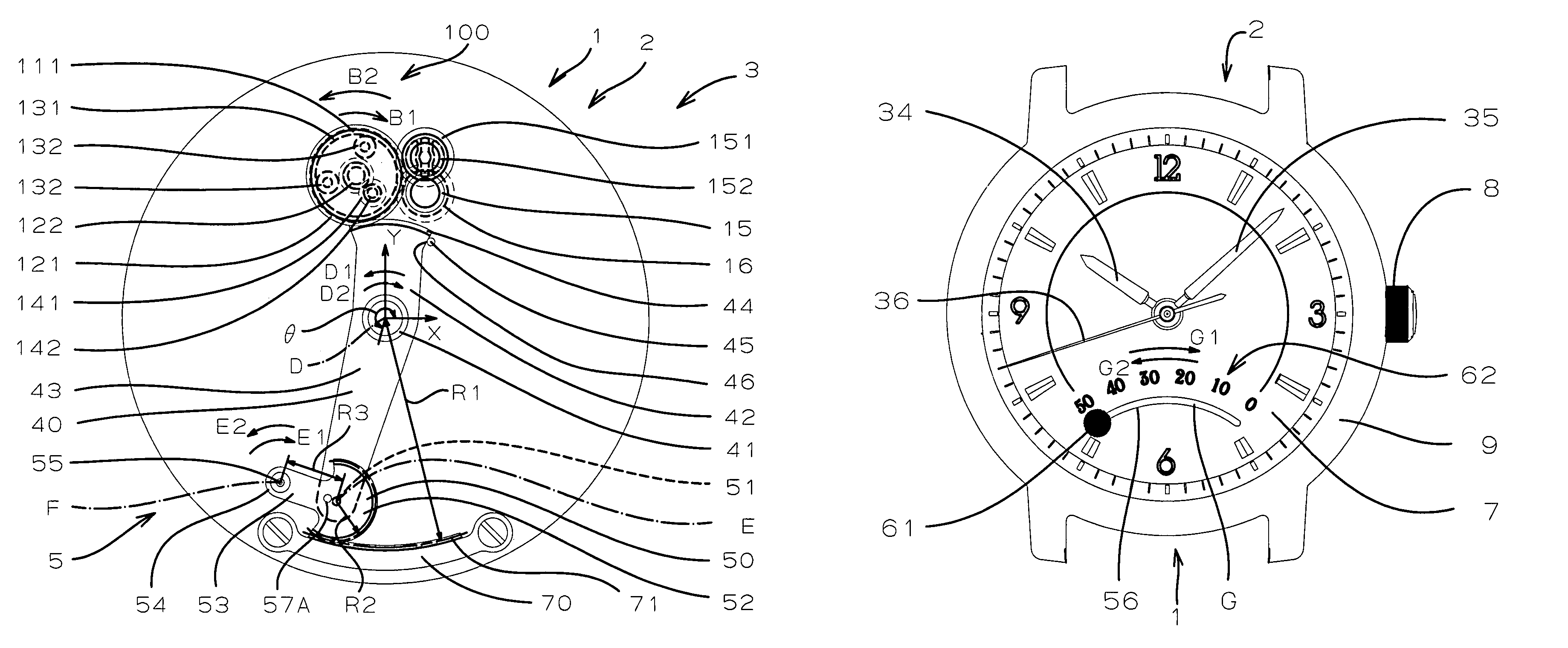
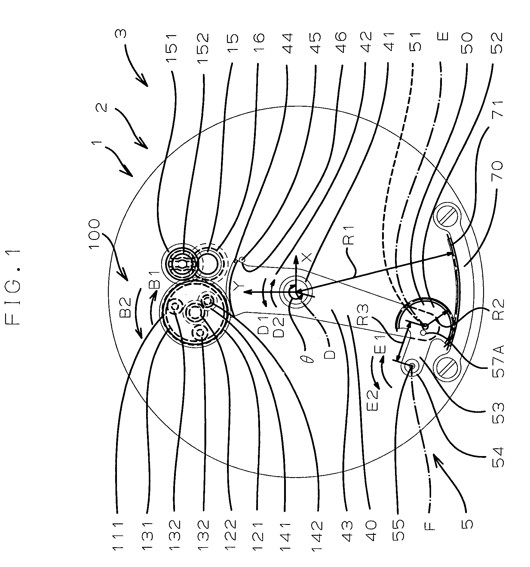
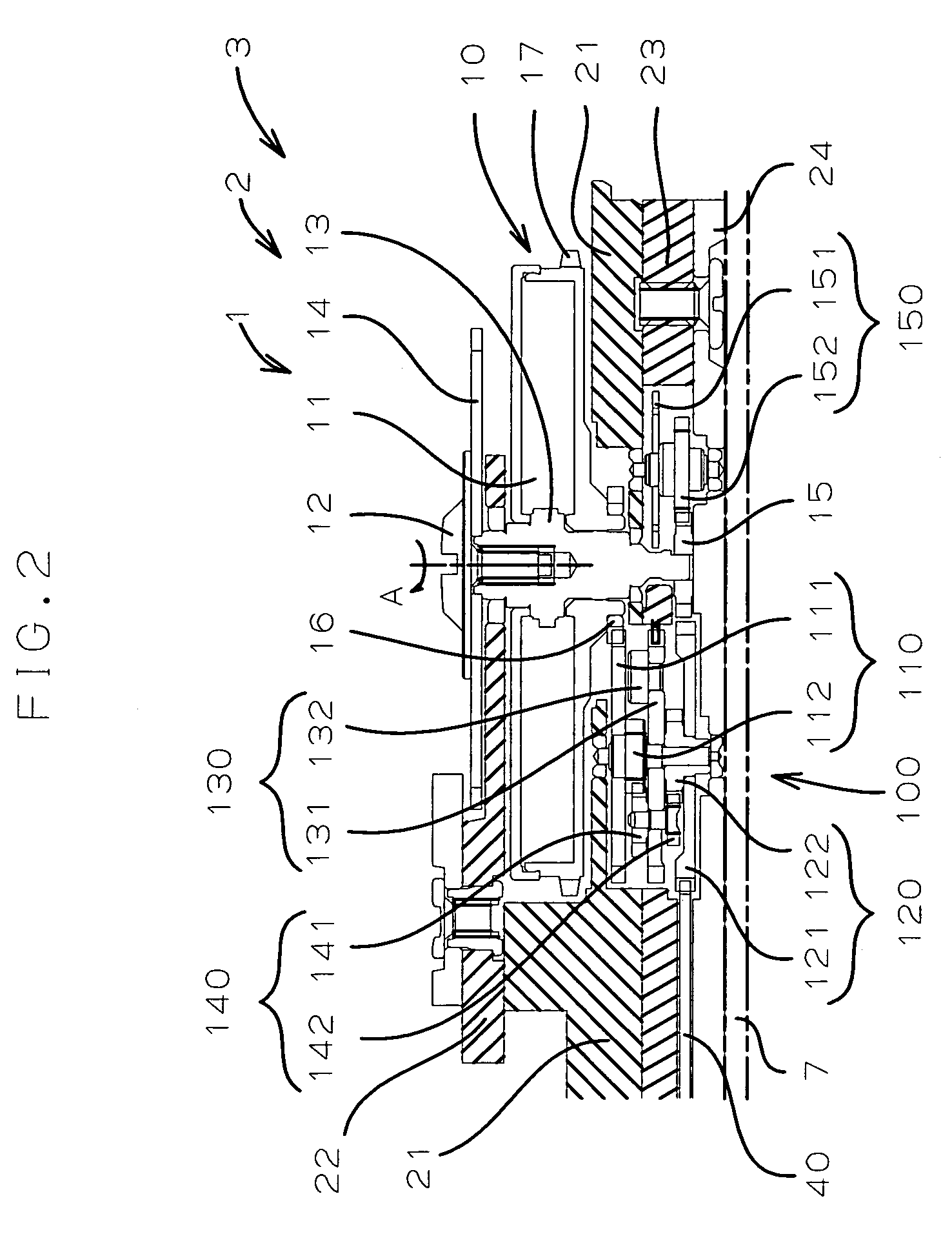
[0049]In FIG. 1-FIG. 3, there is shown a main body part or a movement 3 of a mechanical timepiece 2 possessing a residual wound quantity display mechanism 1 of one desirable embodiment of the present invention.

[0050]As shown in FIG. 2, the movement 3 of the timepiece 2 possesses a barrel drum 10 and, as understood from FIG. 1, the residual wound quantity display mechanism 1 has a planetary wheel mechanism or a planetary unit 100 and a residual wound quantity display mechanism main body part 5. In this example, the movement 3 includes, as stationary support bodies, a main plate 21, a barrel bridge 22, and main plate 23, a 2nd train wheel bridge 24, a center wheel bridge 25 (FIG. 3), and the like.

[0051]The barrel drum 10 possesses in its inside a mainspring 11, and the mainspring 11 is wound in compliance with a rotation of a ratchet wheel 14 fixed to a barrel arbor 13 by a ratchet wheel screw 12. When winding the mainspring 11, a barrel arbor pinion 15 attached to the barrel arbor 13...


PUM


Abstract

To provide a residual wound quantity display mechanism of a timepiece, in which it is possible to change a way of a display without changing a basic structure, and a timepiece with the mechanism concerned. A residual wound quantity display mechanism of a mechanical timepiece has an output gearwheel rotating in compliance with a change in a residual wound quantity of a mainspring; a drive lever possessing monolithically a fan-shaped gearwheel part meshing with the output gearwheel, and an arm part extending from a rotation center of the fan-shaped gearwheel part in a direction different from a fan-shaped portion of the fan-shaped gearwheel part; a display member possessing a drive gearwheel part rotatably supported to a tip part of the arm part of the drive lever, and a display arbor formed monolithically in the drive gearwheel part in a site separated from a rotation center of the drive gearwheel part; and a fixation gearwheel possessing a fixation tooth part with which a tooth part of the drive gearwheel part of the display member meshes. Typically the fixation gearwheel adopts a form of the internally-toothed gearwheel.

Description

BACKGROUND OF THE INVENTION[0001]1. Field of the Invention[0002]The present invention relates to a residual wound quantity display mechanism of a timepiece, and a timepiece with the residual wound quantity display mechanism.[0003]2. Description of the Related Art[0004]In a timepiece in which at least one part of a drive source is a mainspring, there is proposed an attempt conceiving an idea in a display of a residual wound quantity or a power reserve quantity (residual mainspring-wound quantity or residual mainspring quantity) (e.g., Patent Documents JP-A-2005-214655 Gazette, JP-A-2006-234432 Gazette and JP-A-2006-234433 Gazette).[0005]JP-A-2005-214655 discloses about a residual wound quantity display mechanism made so as to display the residual mainspring quantity by driving a winding display wheel in a place separated from an output gearwheel rotating in compliance with a change in the residual wound quantity of the mainspring by using a gearwheel (here, called a segment gearwheel...

Claims


Application Information

Patent Timeline
Patent Type & Authority Patents(United States)
IPC IPC(8): G04B9/00
CPCG04B9/005
Inventor WATANABE, MAMORU
Owner SEIKO INSTR INC
Learn More