
Bus bar for electric connection and middle and battery module comprising the same

a battery module and bus bar technology, applied in the field of electric connection and a medium or large-sized battery module, can solve the problems of accelerated unit cell fire or explosion, and deterioration of the unit cell, and achieves excellent electrical characteristics, easy electrical connection, and excellent mechanical strength

Active Publication Date: 2009-11-03
LG ENERGY SOLUTION LTD
View PDF14 Cites 20 Cited by
  • Summary
  • Abstract
  • Description
  • Claims
  • Application Information

AI Technical Summary

Benefits of technology

[0011]Specifically, it is a first object of the present invention to provide a bus bar for electrical connection that is capable of easily accomplishing electrical connection and mechanical coupling in a medium- or large-sized battery module or battery pack and that has excellent electrical characteristics, such as electrical resistance at connected regions after the electrical connection, and excellent mechanical strength against external impacts or vibrations.
[0012]The bus bar prevents occurrence of short circuits, which may be caused by a user or an operator, during a manufacturing process of the battery module or the battery pack or during a maintenance process of the battery module or the battery pack. Furthermore, the size of the battery pack is further decreased through the use of the bus bar.
[0013]It is a second object of the present invention to provide a battery module wherein the electrical connection between unit cells is accomplished using the bus bar and the unit cells are directly connected to a battery management system (BMS) for detecting voltage and / or temperature of the unit cells using the bus bar, whereby the use of additional connecting members is not necessary, and therefore, the battery module is manufactured in a compact structure, the electrical connection between the unit cells is stable, and the durability, including the mechanical characteristics, of the battery module is excellent.
[0025]Various kinds of secondary batteries may be used as the unit cells. Preferably, plate-shaped batteries, which can be stacked with high integration, are used as the unit cells. More preferably, pouch-shaped batteries, which can be manufactured with small manufacturing costs and are light in weight, are used as the unit cells.
[0027]While the two unit cells are mounted in each of the battery cartridges, the electrode terminals of each unit cell protrude toward the upper ends of the frame members (a, b, c). In a preferred embodiment of the present invention, the inner frame member (c) is provided at a predetermined position corresponding to one of the electrode terminals (the cathode terminal or the anode terminal) of the upper end thereof with a skirt, which extends along the corresponding electrode terminal, and the base plate is provided at a predetermined position corresponding to the skirt with a groove, in which the skirt is engaged. This structure of the skirt and the groove prevents occurrence of electrical short circuits, which may be caused by incorrect connection of the cathode and the anode when the base plate, to which the bus bars are mounted, is assembled with the battery cartridges, as will be described below in detail, and accurately sets the coupling positions of the base plate and the battery cartridges.
[0029]Preferably, the outer frame members (a, b) are provided at the upper ends thereof with locating parts, at which the electrode terminals of the unit cells are located while being bent, and the outer frame members are provided under the locating parts thereof with depressions, which extend in the lateral direction of the unit cells, the locating parts having pluralities of welding grooves, which extend in the longitudinal direction of the outer frame members such that the welding grooves can communicate with the depressions, whereby the welding operation is easily carried out. Consequently, when a welding operation, for example, a resistance welding operation (or a spot welding operation) is carried out while the plurality of battery cartridges are stacked, one welding tip is connected to the lower ends of the electrode terminals on the locating parts through the depressions and the welding grooves, and another welding tip is connected to the upper ends of the bus bars. It has been proved that the welding grooves are helpful even when a laser welding operation is carried out at the upper ends of the bus bars.

Problems solved by technology

However, the closed-type battery module has problems in that heat generated in the unit cells is accumulated, and therefore, the accumulated heat accelerates the deterioration of the unit cells and that some of the unit cells are overheated when they are operated abnormally, and therefore, the unit cells may catch fire or explode.
When such heat is continuously accumulated in the unit cells, the deterioration of the unit cells is accelerated, and furthermore, the unit cells may catch fire or explode.
As a result, a possibility of short circuits exists, and it is not possible to perform welding or mechanical coupling using bolts and nuts.
However, these conventional methods have several problems in that the mechanical strength or the resistance to vibrations is low, contact resistance is increased due to corrosion, and connected parts are easily separated from each other.
Also, the medium- or large-sized battery module or battery pack includes a plurality of unit cells, and the operating performance of the system is deteriorated due to overheating of some unit cells and high potential difference between the unit cells.
However, the use of a large amount of components in a compact battery module or battery pack may cause the above-described problems.

Method used


Image

  • Bus bar for electric connection and middle and battery module comprising the same
  • Bus bar for electric connection and middle and battery module comprising the same
  • Bus bar for electric connection and middle and battery module comprising the same

Examples


Embodiment Construction

[0053]Now, preferred embodiments of the present invention will be described in detail with reference to the accompanying drawings. It should be noted, however, that the scope of the present invention is not limited by the illustrated embodiments.

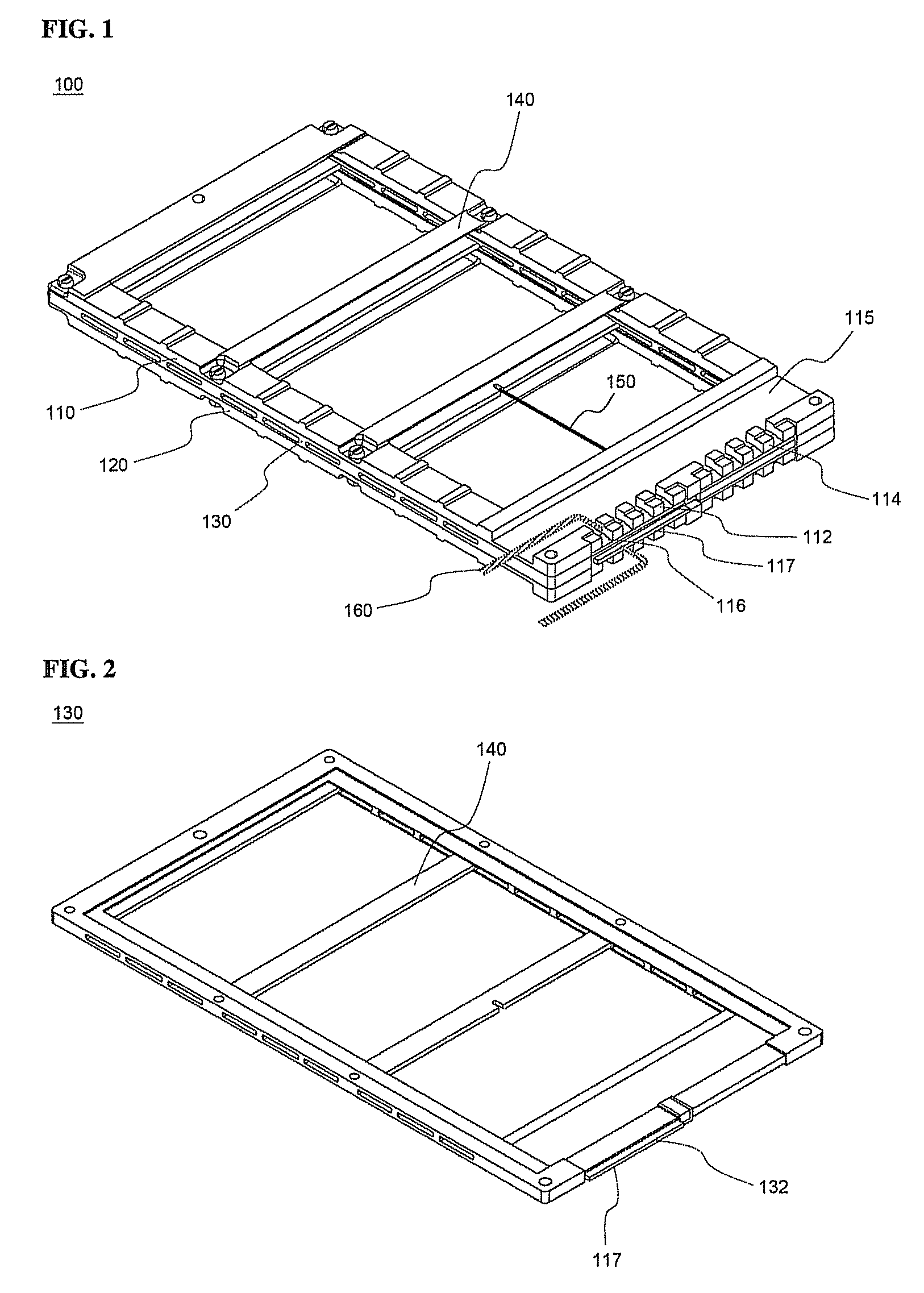
[0054]FIG. 1 is a perspective view typically illustrating a battery cartridge according a preferred embodiment of the present invention.

[0055]Referring to FIG. 1, the battery cartridge 100 includes a pair of outer frame members 110 and 120, and an inner frame member 130 disposed between the outer frame members 110 and 120. The details of the frame members 110, 120, and 130 are described in Korean Patent Application No. 2004-111699, which has been filed in the name of the applicant of the present application.

[0056]Two unit cells (not shown) are mounted in a hollow part between the first outer frame member 110 and the inner frame member 130 and in another hollow part between the second outer frame member 120 and the inner frame member 130, res...


PUM

PropertyMeasurementUnit
voltageaaaaaaaaaa
temperatureaaaaaaaaaa
unit cellsaaaaaaaaaa

Abstract

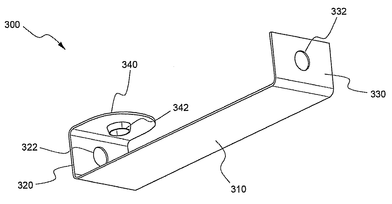
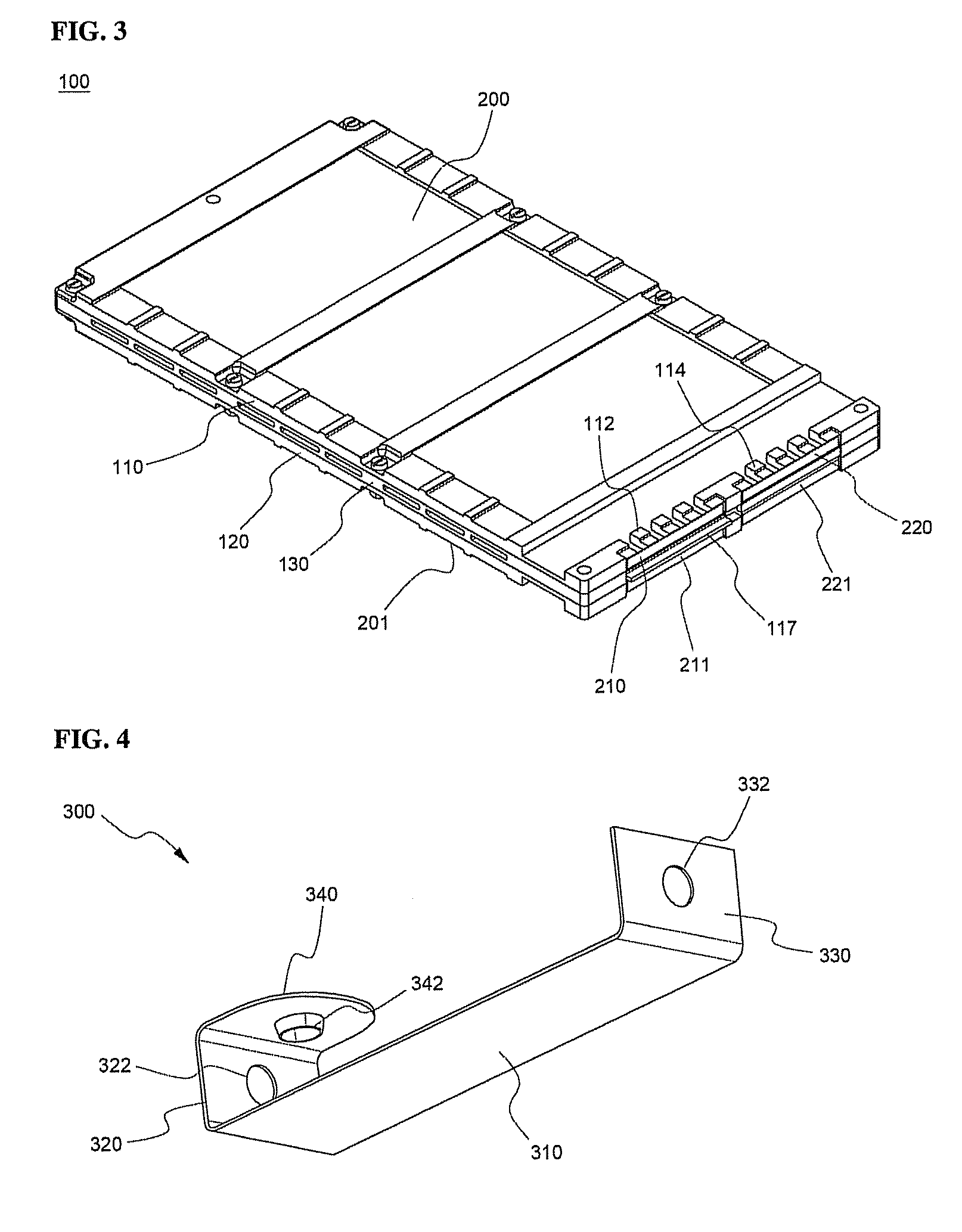
A bus bar simultaneously performs electrical connection between unit cells and detection of voltage of the unit cells in a battery module having the same and includes: vertical bent parts formed by bending opposite ends of a strip-shaped bar body in the same direction, the vertical bent parts being provided with coupling grooves or protrusions; and a horizontal bent part formed by bending one of the vertical bent parts toward the bar body such that the horizontal bent part is parallel with the bar body. The electrode terminals of the unit cells are connected to the rear surface of the bar body of the bus bar, whereby the electrical connection between the unit cells is accomplished, and the horizontal bent part of the bus bar is directly connected to a battery management system for monitoring the potential difference and the temperature of the unit cells to control the unit cells.

Description

FIELD OF THE INVENTION[0001]The present invention relates to a novel bus bar for electrical connection and a medium- or large-sized battery module including the same, and, more particularly, to a bus bar that simultaneously performs the electrical connection between a plurality of unit cells and the detection of voltage of the unit cells in a battery module having the unit cells mounted therein, wherein the bus bar includes vertical bent parts formed by bending opposite ends of a strip-shaped bar body in the same direction, respectively, the vertical bent parts being provided with coupling grooves or protrusions, and a horizontal bent part formed by bending one of the vertical bent parts such that the horizontal bent part is parallel with the bar body, and a battery module including a plurality of unit cells, wherein the electrical connection between the unit cells and the detection of voltage of the unit cells are simultaneously performed using the bus bar.BACKGROUND OF THE INVENTI...

Claims


Application Information

Patent Timeline
Patent Type & Authority Patents(United States)
IPC IPC(8): H01M10/48H01B5/02H01M6/42H02B1/20H01M50/211H01M50/244H01M50/284H01M50/507H01M50/51H01M50/522H01M50/569
CPCH01M2/1072H01M2/206H01M10/42H01M10/482H01M10/425H01M10/5032H01M10/5004H01M10/5016H01M10/625H01M10/647H01M10/613Y02E60/10H01M50/507H01M50/522H01M50/284H01M50/51H01M50/569H01M50/211H01M50/244
Inventor YOON, JUNILLKIM, JUYOUNG
Owner LG ENERGY SOLUTION LTD
Learn More