
Seat back adjustment mechanism

a seat back and adjustment mechanism technology, applied in the field of seats, can solve the problems of not including a balanced seat back adjustment device, unable to work with a compliant back member similar to that known, and significant packaging drawbacks in terms of packaging

Inactive Publication Date: 2009-11-03
ADIENT LUXEMBOURG HLDG SARL
View PDF11 Cites 59 Cited by
  • Summary
  • Abstract
  • Description
  • Claims
  • Application Information

AI Technical Summary

Benefits of technology

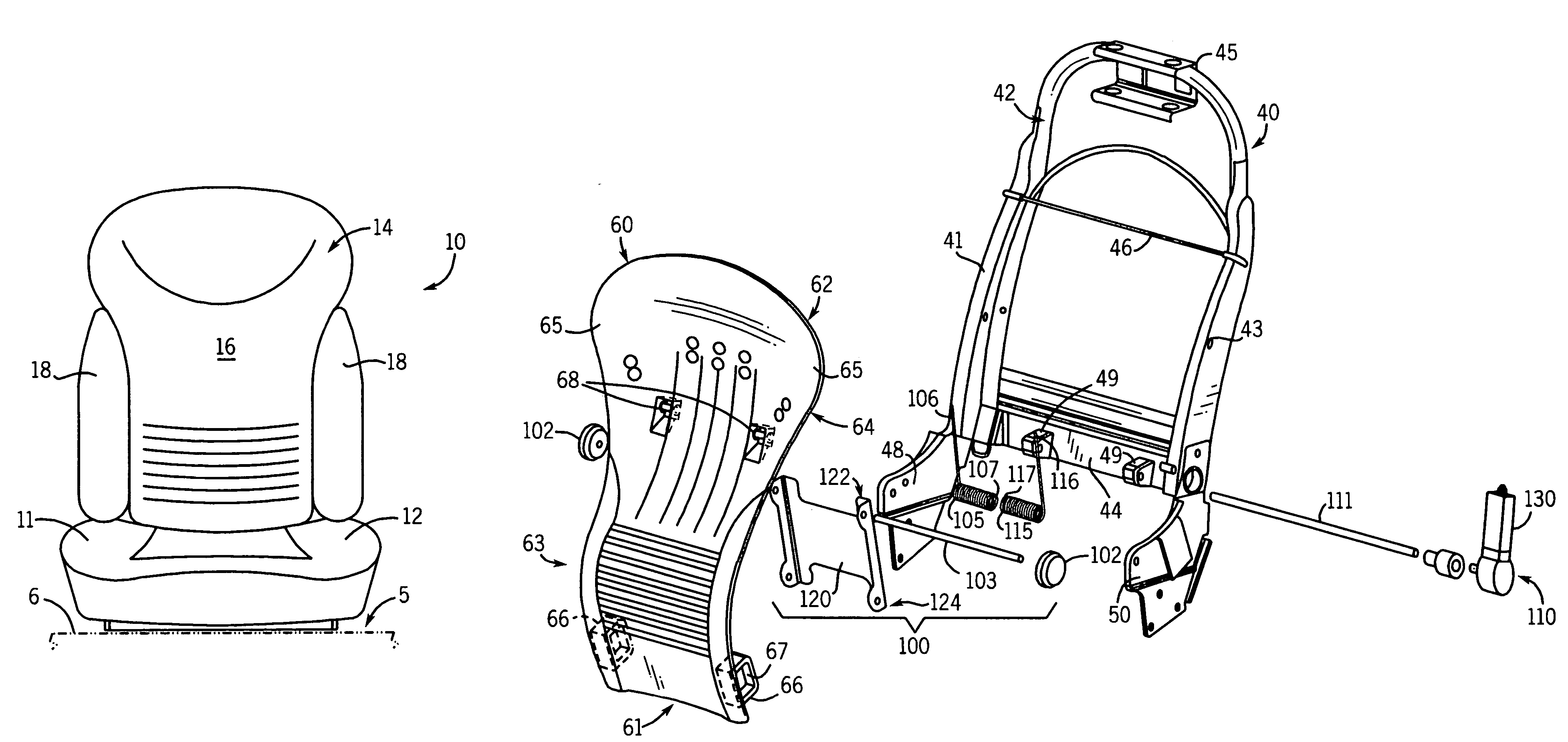
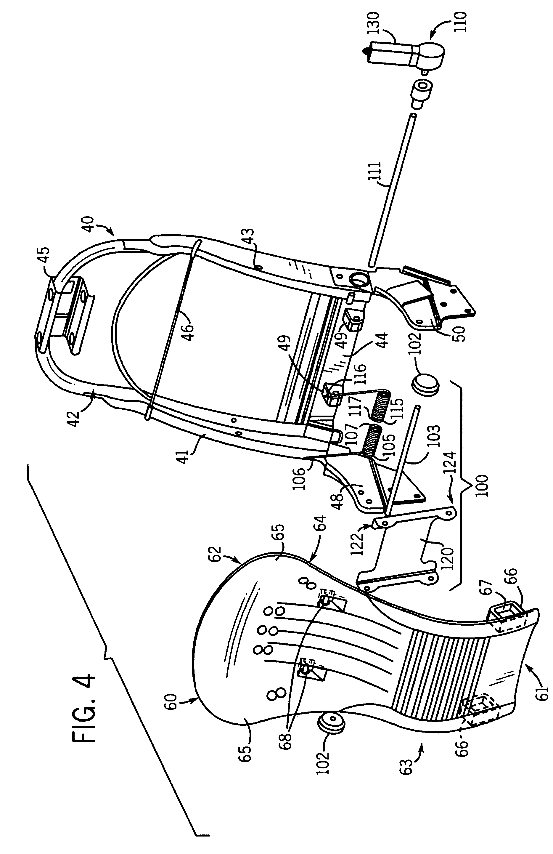
"The invention is a vehicle seat with a compliant back that is connected to a seat frame using a slidable pivot member. The compliant back is also connected to a seat back biasing member that includes two spring members that bias the compliant back against the seat frame. The biasing member can be adjusted to adjust the tension of the spring members using a drive motor. The technical effect of this invention is to provide a vehicle seat that provides better support and comfort for the occupant while also allowing for adjustable biasing of the compliant back to improve the overall performance of the seat."

Problems solved by technology

The prior art office chair has significant drawbacks in terms of its packaging and that it does not include a balanced seat back adjustment device for controlling the compliant back member.
However, none of these devices are capable of working with a compliant back member similar to that known in the prior art.
Further, none of the known adjustable lumbar devices disclose or teach an adjustment mechanism having sufficient strength and robustness as required to apply the compliant back member of the known chair art to a vehicle seat.

Method used


Image

  • Seat back adjustment mechanism
  • Seat back adjustment mechanism
  • Seat back adjustment mechanism

Examples


Embodiment Construction

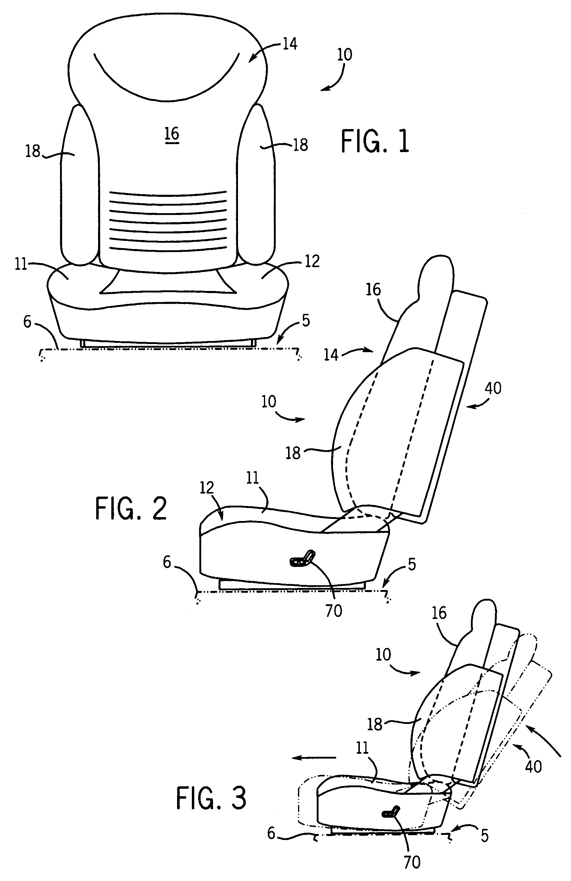
[0014]Before beginning the detailed description of the preferred and exemplary embodiments, several general comments are warranted about the applicability and the scope of the present invention. First, the illustrations relate to a seat (also referred to as a chair) particularly adapted for motor vehicles, such as cars, SUVs, vans, trucks, buses and the like, but the invention is applicable also to seating used in other vehicles such as aircraft, railroad, nautical or others as well as other non-vehicle applications such as office chairs and other similar environments.

[0015]Second, the seat of the present invention is illustrated in the first few FIGURES as a padded seat having certain contours, trim and the like. While this configuration is presently preferred, a wide variety of seat configurations and appearances will benefit from use of the mechanical support and movement mechanisms described in connection with the later FIGURES. Also the exterior of the seat can be covered by fa...


PUM


Abstract

A seat for use by an occupant in a vehicle. The seat includes a seat base configured to be supported in the vehicle. A back frame including a first transverse member, a first side member and a second side member, wherein the first transverse member interconnects each of the side members at a location toward an upper end of the back frame. The back frame further includes a second transverse member interconnecting the first and second side members a spaced distance from the first transverse member. A compliant back member having a first end operably connected to the first transverse member and a second end operably connected to the second transverse member. A biasing member having a first end operatively engaging the compliant back member and a second end being anchored with respect to the back frame wherein when a seat occupant's back applies a force to the compliant back member, the biasing member applies a reaction force.

Description

CROSS-REFERENCE TO RELATED PATENT APPLICATIONS[0001]This application is the National Phase application of International Application No. PCT / US2004 / 036912 filed Nov. 5, 2004 and this application claims the benefit of U.S. Provisional Application No. 60 / 519,304 filed Nov. 11, 2003, and incorporated herein by reference in its entirety.FIELD[0002]The present invention relates generally to the field of seats and more particularly relates to a seat having a compliant back member such as an automotive seat having a seat back having a flexible member.BACKGROUND[0003]It is known to provide a chair or seat having a compliant back member pivoted to a seat back frame assembly in at least two vertically spaced-apart locations for providing a controlled curvilinear flexure support. For examples of the above, see U.S. Pat. Nos. 5,871,258; 5,909,923; 5,975,634; 5,979,984; 6,079,785; 6,086,153; 6,220,661 which disclose a office chair including a compliant back member. The prior art office chair has ...

Claims


Application Information

Patent Timeline
Patent Type & Authority Patents(United States)
IPC IPC(8): A47C1/024B60N2/02A47C7/46B60N2/22B60N2/66B60N2/68
CPCB60N2/0232B60N2/68B60N2/66B60N2/22B60N2/667B60N2/6673B60N2/986B60N2/02246
Inventor MICHALAK, ERIC BERNARDBENZING, ROBERT MICHAELHENSEL, DAVID
Owner ADIENT LUXEMBOURG HLDG SARL
Learn More