Drum type washing machine

a drum type and washing machine technology, applied in other washing machines, domestic applications, textiles and papermaking, etc., can solve the problems of undesired extension of the duration complex programming of the water extraction process based on such numerous factors, and inability to completely eliminate the residual water at the bottom portion, etc., to achieve desired rinsing efficiency, reduce water extraction time, and eliminate problems such as operational failure

Inactive Publication Date: 2009-10-27
PANASONIC CORP
View PDF18 Cites 2 Cited by
  • Summary
  • Abstract
  • Description
  • Claims
  • Application Information

AI Technical Summary

Benefits of technology

[0009]It is, therefore, an object of the present invention to provide a drum type washing machine capable of reducing water-extracting times and obtaining desired rinsing efficiency, while eliminating problems such as operational failure from excessive suds during a water-extracting cycle.

Problems solved by technology

As for the conventional water-extracting process, although the drum is spun at a low rpm or subjected to an intermittent rotation in the initial stage of the water-extracting cycle to wring out wash water from the laundry, it has been impossible to completely eliminate residual water collecting at the bottom portion of the water tub due to various factors such as the water drain-hose layout or different laundry types which can affect the performance of the draining system.
Because programming a water-extracting process based on such numerous factors is complicated, it is performed assuming the worst conditions for these factors.
Consequently, the duration of the low-rpm or intermittent rotations of the drum is usually set to be excessively long, thereby undesirably extending the duration of the water-extracting process even if it may be unnecessary.
Further, if the water-extracting cycle is started while the clothes in the drum are entangled after the wash cycle, the overall weight distribution in the drum can be imbalanced during the water-extracting cycle.
As a result, excessive suds are generated as the wash water in the water tub contacts the drum, thereby causing an operational failure.
Further, since the rotational number of the drum cannot be increased above the vibration resonance point, desired rinsing and water-extracting performance cannot be obtained.

Method used


Image

  • Drum type washing machine
  • Drum type washing machine
  • Drum type washing machine

Examples


first preferred embodiment

[0019]Hereinafter, preferred embodiments of the present invention will be described with reference to the accompanying drawings. Here, it is to be noted that the present invention is not limited thereto.

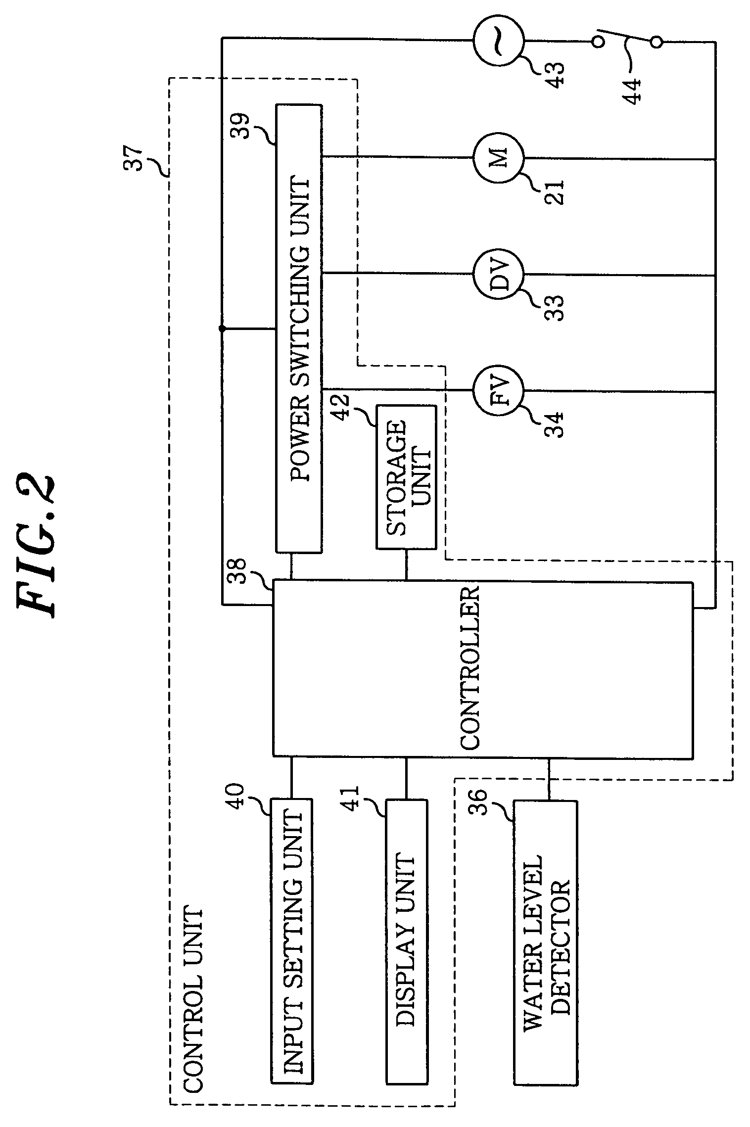
[0020]FIG. 1 is a lateral cross sectional view of a drum type washing machine in accordance with a first preferred embodiment of the present invention. As shown in the figure, cylindrical rotary drum 17 having a bottom surface is provided with multiple drum perforations 18 in its cylindrical surface and is rotatably installed in water tub 19. Further, rotary drum 17 is also provided with rotating shaft (central axis of rotation) 20 at its center of rotation and is arranged such that its central axis of rotation is declined from the front side of the drum type washing machine toward the rear side thereof. Further, motor 21 installed at the rear portion of water tub 19 is connected to rotating shaft 20, so that rotary drum 17 is driven by motor 21 to rotate in a clockwise and countercl...

second preferred embodiment

[0039]Referring to FIGS. 4A and 4B, there are provided a cross sectional view and a perspective view of the areas around water outlets 49a and 49b provided in drain groove 30, respectively. Water outlets 49a and 49b are provided with guiding surface 48 of guiding member 47 disposed therebetween. The rest of the configurations are identical to those described in the first embodiment, so they will not be discussed, while assigning like reference numerals thereto.

[0040]In the above configuration, residual wash water collected in the rear side portion (downstream of water flow indicated by arrow A) of guiding surface 48 of guiding member 47 can be completely drained through water outlet 49b. Therefore, very little wash water remains in drain groove 30.

[0041]Moreover, since the configurations, functions and effects of guiding member 47, guiding surface 48 and water outlet49a in the washing and water-extracting cycles are identical to those of guiding member 45, guiding surface 46 and wat...

third preferred embodiment

[0043]Referring to FIGS. 5A and 5B, there are provided a cross sectional view and a perspective view of the areas around water outlet 31 provided in drain groove 30, respectively. Guiding surface 51 of guiding member 50 is shaped so it concaves down, and a bottom portion of guiding surface 51 of guiding member 50 is disposed such that it divides water outlet 31 into two parts. Further, in order to make the level drop between water tub 19 and drain groove 30 less abrupt, sidewall 30a of drain groove 30 is provided with sloped surface 52. Also, guiding member 50 is provided with side walls to connect both ends of guiding surface 51 to sidewall 30a. The other configurations are identical to those described in the first embodiment, and their discussion will be omitted, while assigning like reference numerals thereto.

[0044]By shaping guiding surface 51 of guiding member 50 to concave down as above, turbulent flow of suds and wash water can be avoided and controlled, so that they can be d...


PUM


Abstract

A drum type washing machine includes a water tub; a cylindrical rotary drum rotatably installed in the water tub such that a central axis of rotation of the rotary drum is horizontal or slanted; a water outlet provided on a bottom portion of the water tub; a motor for rotating the rotary drum; a water supplying unit for supplying wash water into the water tub; a water draining unit for draining the wash water from the water tub; and a controller for controlling the motor, the water supplying unit and the water draining unit to thereby perform a washing, a rinsing and a water-extracting process. A guiding member with a guiding surface is installed on an inner bottom portion of the water tub to facilitate collection of the wash water and guide the collected wash water toward the water outlet during the water-extracting process.

Description

FIELD OF THE INVENTION[0001]The present invention relates to a drum type washing machine for washing laundry loaded in a rotary drum.BACKGROUND OF THE INVENTION[0002]A conventional drum type washing machine is shown in FIG. 7. Below its configuration is described.[0003]As shown in FIG. 7, drum 1 provided with multiple drum perforations 2 in its cylindrical surface is rotatably installed in water tub 3. One end of rotating shaft 4 is fixed at the center of rotation of drum 1, and its other end is connected to drum pulley 5. Motor 6 is connected to drum pulley 5 via belt 7, so that it can rotate drum 1. An opening of drum 1 is opened or closed by door 8. Water tub 3 is suspended from washing machine main body 9 via springs 10 and supported therein via vibration damper 11 in such a way that vibrations of water tub 3 are not transmitted to washing machine main body 9 during a water-extracting process. Further, water tub 3 is also provided with balancing weight 12 for absorbing the vibra...

Claims


Application Information

Patent Timeline
Patent Type & Authority Patents(United States)
IPC IPC(8): D06F39/08
CPCD06F39/083D06F35/00D06F34/14D06F37/42D06F39/06D06F37/04
Inventor SUMIDA, KATSUAKITERAI, KENJIKUBO, KOICHI
Owner PANASONIC CORP
Why Eureka
Try Eureka