
Armrest for use with a vehicle seat

a vehicle seat and armrest technology, applied in the field of armrests, can solve the problems of not taking into account the varying body size of different operators, operator's difficulty in carrying out work, and running the risk of strain injuries, etc., to achieve secure and simple stowing of the armrest, restricting the driver's freedom of movemen

Inactive Publication Date: 2009-10-13
VOLVO CONSTR EQUIP AB
View PDF15 Cites 17 Cited by
  • Summary
  • Abstract
  • Description
  • Claims
  • Application Information

AI Technical Summary

Benefits of technology

[0007]An object of the invention is to substantially reduce the aforementioned problem inherent in the prior art and to provide an armrest which affords operators of differing body size an ergonomic working position. It must be possible to achieve this while at the same time retaining a secure and simple stowing of the armrest, without the need to provide any new mechanism for moving the armrest between the operating position, and the raised passive position and without restricting the driver's freedom of movement.
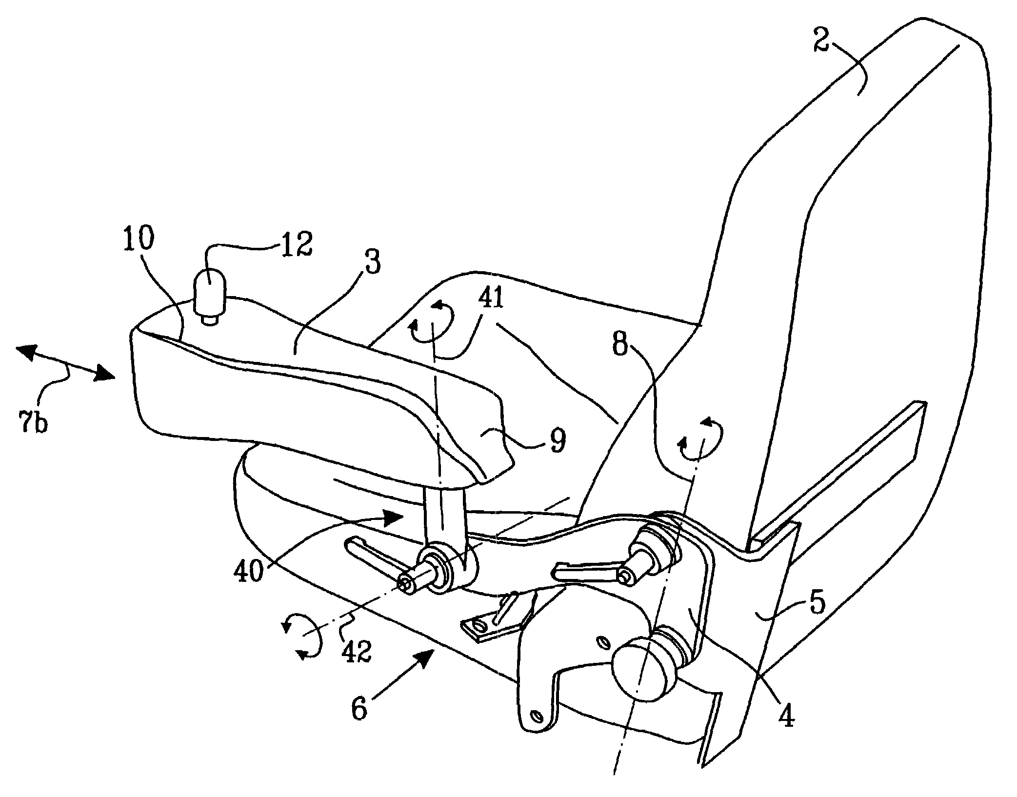
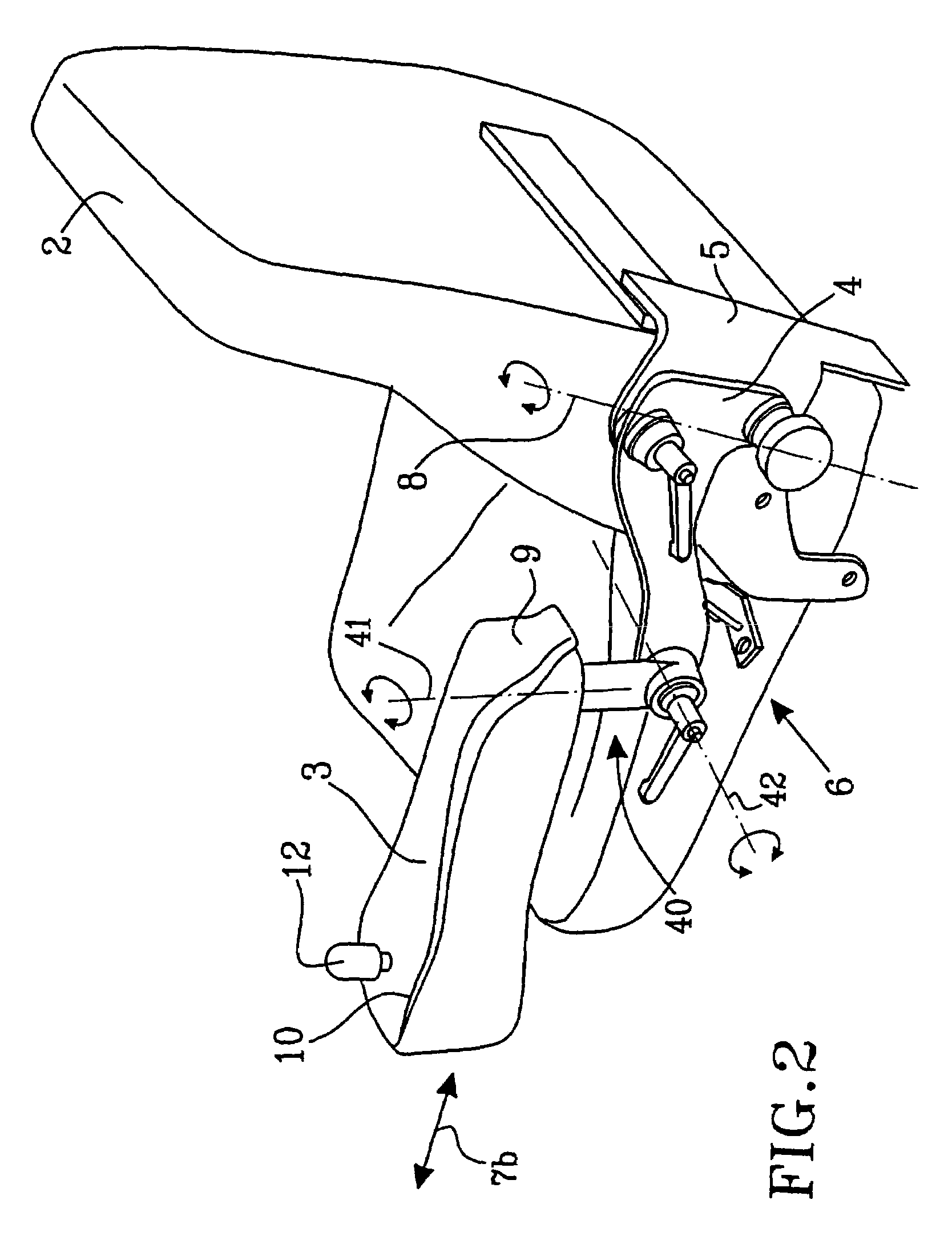
[0008]The objects of the invention are at least in part achieved due to the fact that an adjusting and locking device, which links the first fixing element and the second fixing element in at least two different positions, can be used to set the armrest unit to different positions by moving the armrest unit in a direction having a component in the horizontal plane and aligned so that the position of the armrest unit is laterally variable in relation to the seat. This means that operators themselves can select and set the most favorable distance between the seat and the armrest unit in order to obtain a comfortable working position that is suited to their body size.

Problems solved by technology

Previously known armrests have the disadvantage, however, that they do not take sufficient account of the varying body size of different operators.
An unfavorable working position may mean that the operator finds it more difficult to carry out his work and runs the risk of strain injuries.

Method used


Image

  • Armrest for use with a vehicle seat
  • Armrest for use with a vehicle seat
  • Armrest for use with a vehicle seat

Examples


Embodiment Construction

[0021]FIG. 1 shows a perspective view of an armrest 1 according to the invention and FIG. 2 shows the armrest together with a driver's seat 2 of a vehicle. The armrest comprises (includes, but is not necessarily limited to) a unit 3 for supporting an arm of an operator of the vehicle seated in the seat 2, a first fixing element 4 connected to the armrest unit 3 and a second fixing element 5, which can be fastened to the seat 2 on the vehicle. Although the armrest in the example shown in FIG. 2 is fastened to the driver's seat 2 by means of the second fixing element 5, the armrest in another embodiment could be fastened to another part of the vehicle, such as the vehicle floor, next to the driver's seat, for example.

[0022]The first and the second fixing element 4,5 can be coupled together and can be adjusted and locked in relation to one another by means of a device 6 so as to be able to adjust the position of the armrest unit 3 in relation to the seat 2 when using the armrest. The a...


PUM


Abstract

An armrest (1) for use with a vehicle seat (2), comprising a unit (3) for supporting an arm of an operator of the vehicle seated in the seat, a first fixing element (4) connected to the armrest unit (3) and a second fixing element (5) can be fastened to the seat (2) on the vehicle. The first and the second fixing element can be adjusted and locked in relation to one another by means of a device (6) for adjusting the position of the armrest unit (3) in relation to the seat when using the armrest. When using the armrest, the adjusting and locking device (6), which links the first fixing element (4) and the second fixing element (5) in at least two different positions, can be used to set the armrest unit (3) to different positions by moving the armrest unit (3) in a direction having a component in the horizontal plane, aligned so that the position of the armrest unit (3) is laterally variable in relation to the seat (2).

Description

CROSS-REFERENCE TO RELATED APPLICATIONS[0001]The present application is a continuation patent application of International Application No. PCT / SE2004 / 000829 filed 28 May 2004 which was published in English pursuant to Article 21(2) of the Patent Cooperation Treaty, and which claims priority to Swedish Application No. 0301576-5 filed 28 May 2003. Said applications are expressly incorporated herein by reference in their entireties.FIELD OF THE INVENTION[0002]The present invention relates to an armrest for use with a seat in a vehicle. The invention further relates to a vehicle seat provided with such an armrest and to a vehicle incorporating such an armrest.BACKGROUND OF THE INVENTION[0003]The present invention has applications in various types of vehicles but will hereinafter be described (by way of illustration, but in no way imposing limitations on the invention) in its form as an armrest for use in a wheeled loader provided with so-called comfort drive control (CDC). Vehicles of t...

Claims


Application Information

Patent Timeline
Patent Type & Authority Patents(United States)
IPC IPC(8): B60N2/46B60N2/75
CPCB60N2/4633B60N2/464B60N2/4693B60N2/4653B60N2/4646B60N2/767B60N2/797B60N2/777B60N2/77B60N2/773
Inventor ARMO, SVERKERLINDBLOM, JONNY
Owner VOLVO CONSTR EQUIP AB
Learn More