
Method of determining the derivative of an input signal

a technology of input signal and derivative, applied in the field of determining the derivative of input signal, can solve problems such as problematic conventional derivative calculations, and achieve the effect of eliminating phase delay

Inactive Publication Date: 2009-09-08
GM GLOBAL TECH OPERATIONS LLC
View PDF8 Cites 0 Cited by
  • Summary
  • Abstract
  • Description
  • Claims
  • Application Information

AI Technical Summary

Benefits of technology

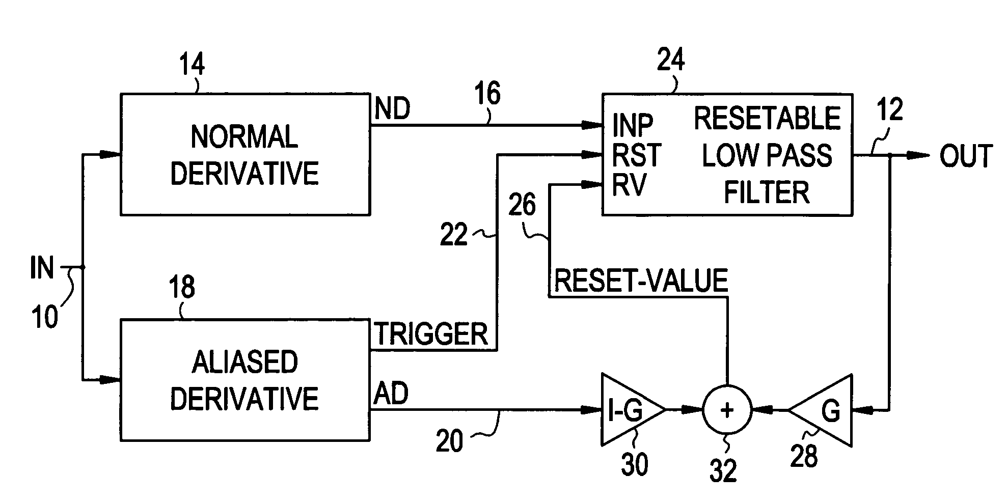
The present invention is a better way to get the derivative of a noisy signal. It uses an aliased derivative to reset a filtered version of the derivative, which is done at a slower rate. This helps to get a more accurate signal. The reset value is determined based on a weighted sum of the aliased derivative and the filter output. This method helps to get a better signal with less delay.

Problems solved by technology

In such an application, conventional derivative calculations are problematic due to the presence of spurious noise in the measured signal, as the derivative of the noise is typically much larger than the derivative of the signal.
However, the filtering introduces phase-delay, which is particularly undesirable if the derivative is to be used for control purposes.

Method used


Image

  • Method of determining the derivative of an input signal
  • Method of determining the derivative of an input signal
  • Method of determining the derivative of an input signal

Examples


Embodiment Construction

[0007]While the method of the present invention may be applied to any type of digital or analog input signal, it is disclosed herein in the context of an application involving a speed transducer and a rotary shaft such as a transmission input or output shaft. In a typical implementation, the speed transducer is positioned in proximity to the periphery of a toothed wheel fixed to the shaft and generates an electrical pulse with the passage of each tooth of the wheel. The pulses are fed to a circuit that produces a digital signal with logic level transitions corresponding to leading and / or trailing edges of the pulses, and the value of a free-running counter is sampled at specified transitions (i.e., zero-to-one, or one-to-zero) of the digital signal. Successive counter samples are differenced to form a succession of time intervals that are inversely proportional to the rotary speed of the shaft. In a dynamic system, the succession of time intervals defines a digital input signal that...


PUM


Abstract

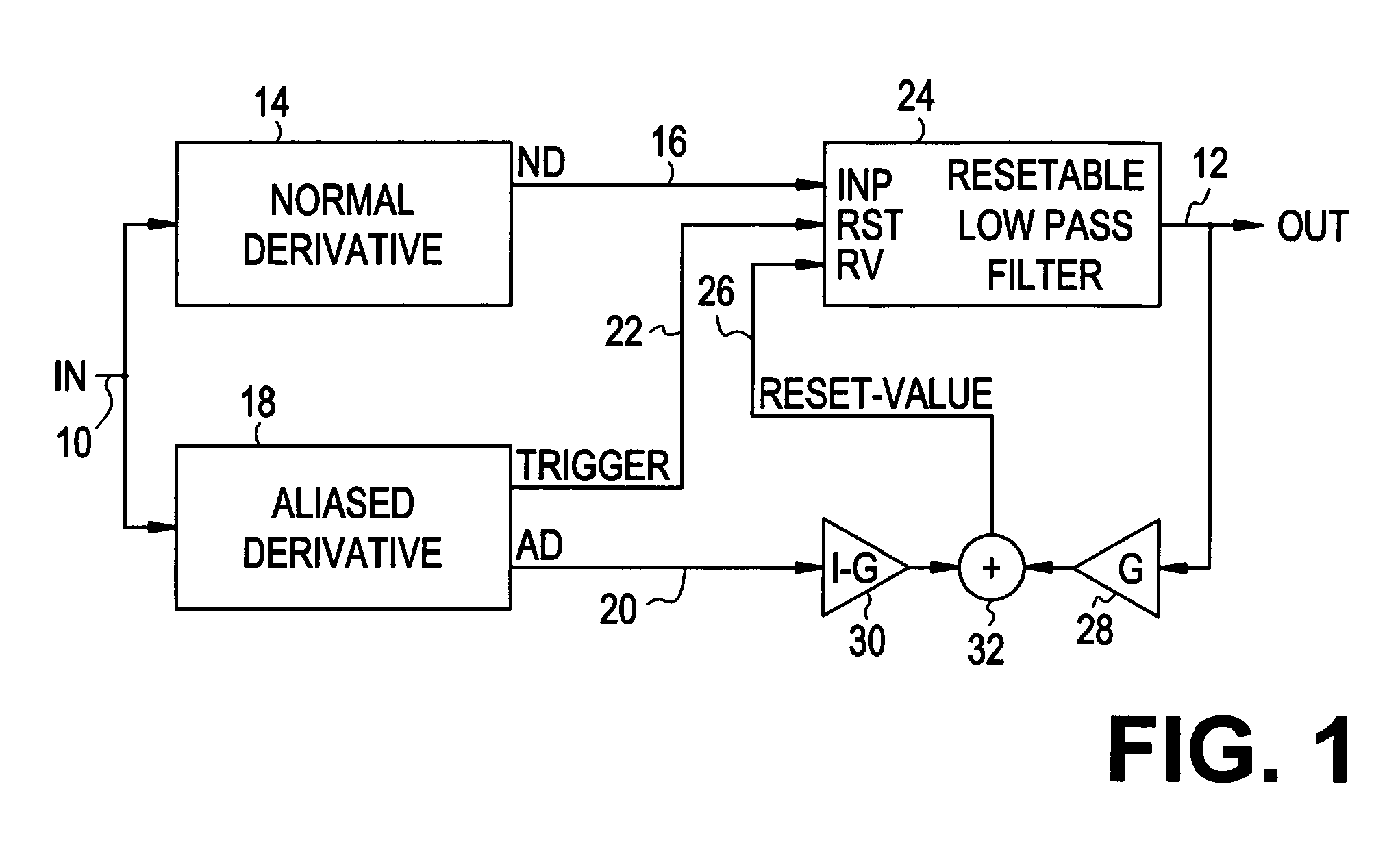
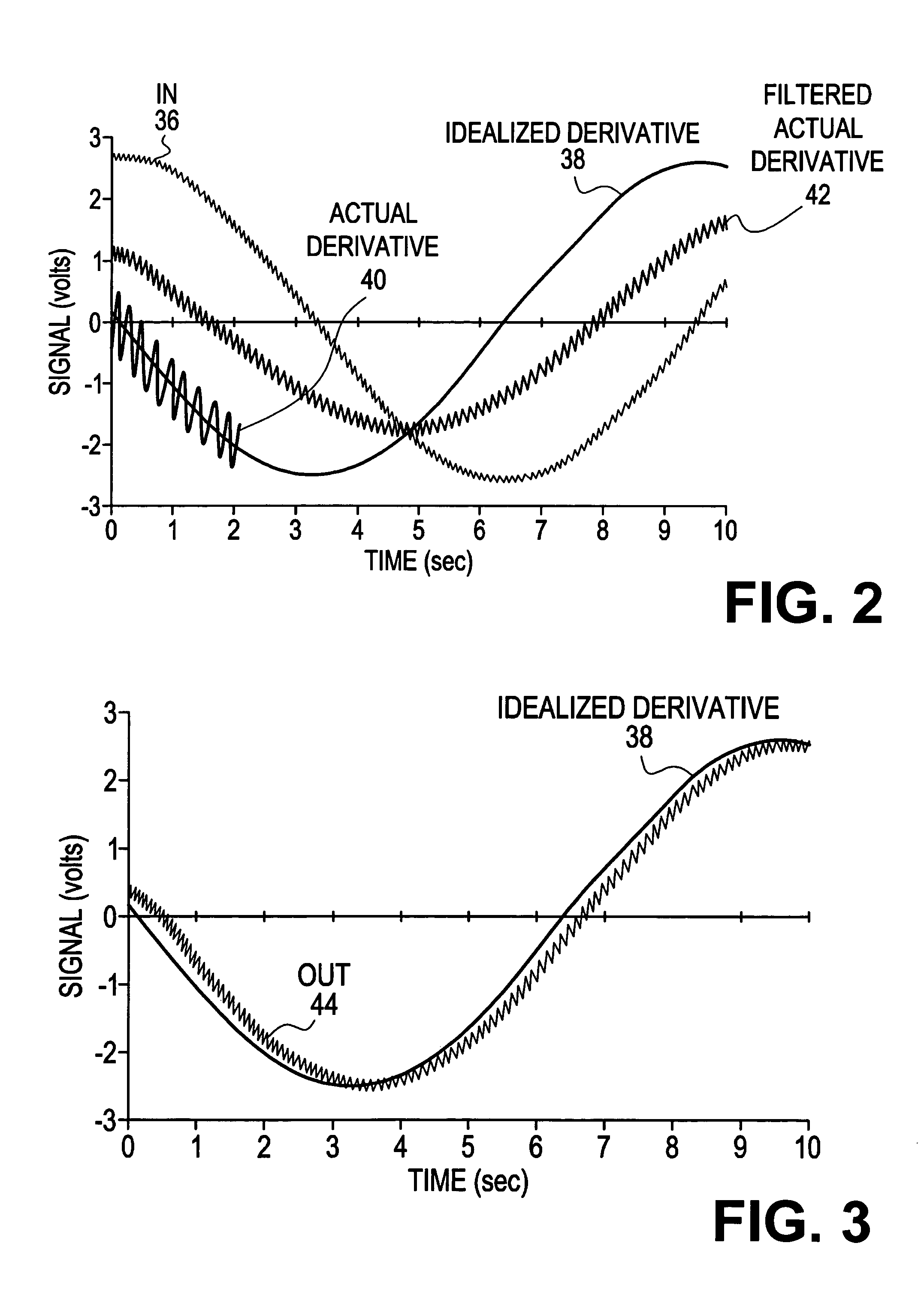
The derivative of a noise-containing input signal is determined by using an aliased derivative to periodically reset a filtered version of a normally determined derivative. The aliased derivative is calculated using a slower update or sampling rate than the normally determined derivative, and the filtered version of the normally determined derivative is reset to a reset value at each update of the aliased derivative. The reset value is based on a weighted sum of the aliased derivative and the filter output. The periodically reset filter output closely follows an idealized derivative of the input signal, substantially eliminating the phase delay introduced by conventional filtering.

Description

TECHNICAL FIELD[0001]The present invention relates to determining the derivative (i.e., the rate of change with respect to time) of a noise-containing input signal without introducing phase delay due to filtering.BACKGROUND OF THE INVENTION[0002]It is commonly necessary in control applications to determine the derivative of a measured input signal. In the control of a motor vehicle transmission, for example, a controller produces a digital speed signal based on the output of a shaft speed sensor, and then determines the acceleration of the shaft by computing the derivative of the speed signal. In such an application, conventional derivative calculations are problematic due to the presence of spurious noise in the measured signal, as the derivative of the noise is typically much larger than the derivative of the signal. The usual approach is to low-pass filter either the input signal or its derivative to remove or severely attenuate the noise-related component. However, the filtering...

Claims


Application Information

Patent Timeline
Patent Type & Authority Patents(United States)
IPC IPC(8): G06F7/00G01D1/10G01D3/028G01P15/16G06F7/38
CPCG01D3/028
Inventor CAWTHORNE, WILLIAM R.SAH, JY-JEN F.
Owner GM GLOBAL TECH OPERATIONS LLC
Learn More