
Auger trough clean-out door

a technology for cleaning out auger troughs and auger troughs, which is applied in the field of auger troughs and, can solve the problems of limited access to certain areas, inability to clean out the auger troughs, and the clean out of the clean grain auger troughs and the clean tailings auger troughs, etc., and achieves the effects of easy reinstallation, effective effect, and severe build-up

Inactive Publication Date: 2009-09-08
BLUE LEAF I P INC
View PDF25 Cites 14 Cited by
  • Summary
  • Abstract
  • Description
  • Claims
  • Application Information

AI Technical Summary

Benefits of technology

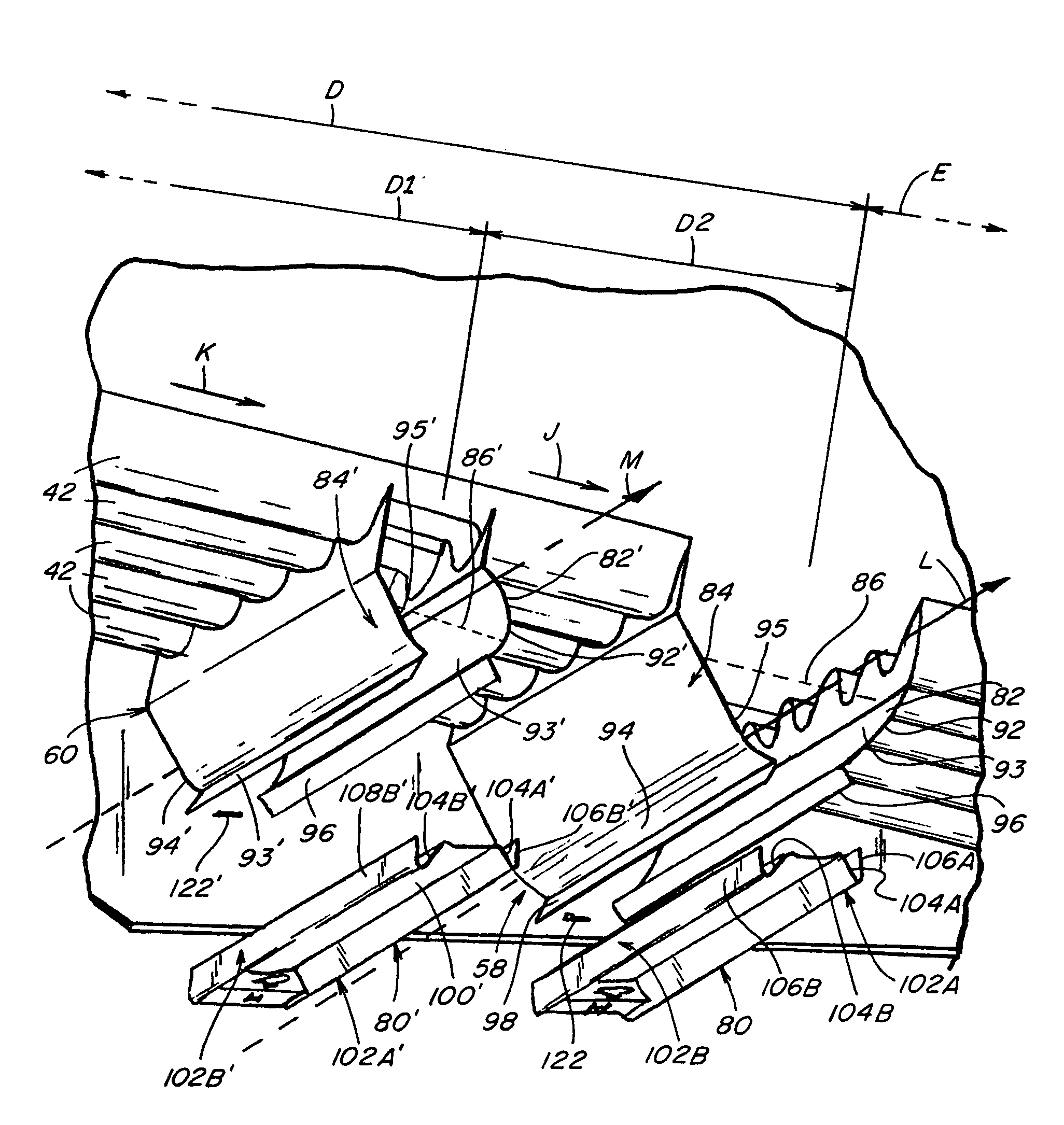
[0014]Preferably, the opposite ends of such door panel are configured to be complementarily engageable with the opposed sidesheets to maintain such door panel in position across the combine between the opposed sidesheets. In one preferred embodiment, the door panel has a first, free end configured to be engageable with and to rest upon a projecting flange on a first of the opposite sidesheets and a second, latch end with an associated latch mechanism for engaging a complementary latching feature on the second of the opposed sidesheets for generally securing the door panel in position along the bottom of the trough.
[0015]By operating the latching mechanism associated with the latch end of the door panel, the door panel can be released from its securement with the second of the opposed sidesheets and such latch end can be rotated downwardly to permit disengagement of the free end from the projecting flange of the first opposed sidesheet and the removal of the door panel. The door panel can be cleaned, and scraped, if necessary, to remove any remnants adhering thereto or encrusted thereupon. When the door panel is removed, remaining loose remnants within the trough will be allowed to fall to the ground, and further cleaning, including by the use of pressurized streams of water or air or by scraping action to remove severe build-up, of the side walls then can be more readily and effectively effected than was true of previous constructions.
[0016]Such door panel embodiment can be readily reinstalled by positioning the free end of the door panel to rest upon the projecting flange on the first opposed sidesheet, rotating the latch end of the door panel upwardly to engage the side walls and to position the latching mechanism and the latching feature for engagement with one another, and operating the latching mechanism to secure the door panel in place.
[0017]With such a construction, the removal and reinstallation of the door panel can be quickly and easily effected from the side of the combine, rather than requiring a user to access the underside of the combine and to engage in cumbersome activities in uncomfortable positions, and better clean out of the trough can be can be realized.

Problems solved by technology

In some combines and with some auger troughs, the ability to clean out the troughs has been essentially limited to the introduction or direction of a pressurized stream of water into the end of an auger trough to try to wash out the remnants remaining therein, with modest success.
Even with such engineered clean-out doors, clean out of the clean grain auger troughs and the tailings auger troughs has remained problemsome due to the difficulties associated with the removal and reinstallion of such doors, due in part to the location of such doors beneath the combine and the necessity for accessing them from beneath the combine, and to the limited accessibility to certain areas along the troughs even when the doors have been removed.
Since such doors have encompassed only a portion of the undersides of the troughs, even when such doors have been removed for clean out activities, remnants of crop and other materials could remain at the ends of the troughs and at other areas along the troughs that are not located above the door locations or to which there would be only limited, if any, accessibility through such doors.

Method used


Image

  • Auger trough clean-out door
  • Auger trough clean-out door
  • Auger trough clean-out door

Examples


Embodiment Construction

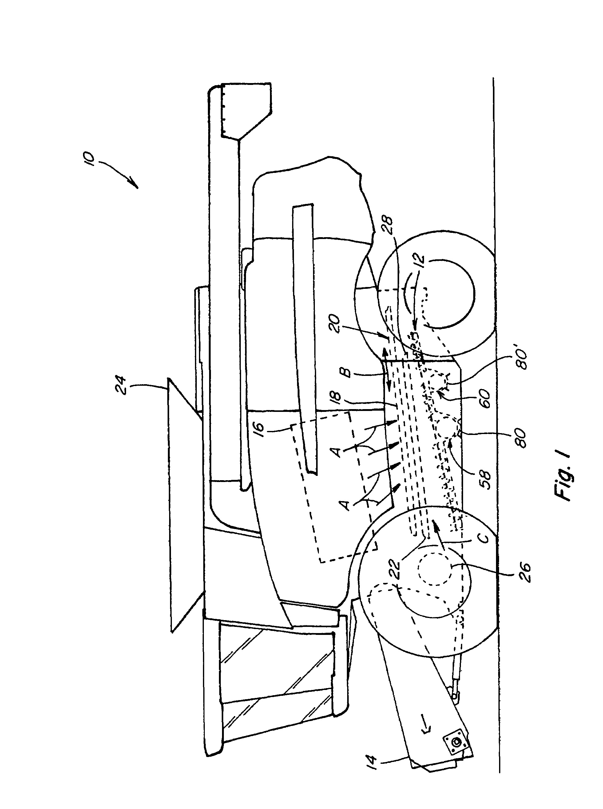
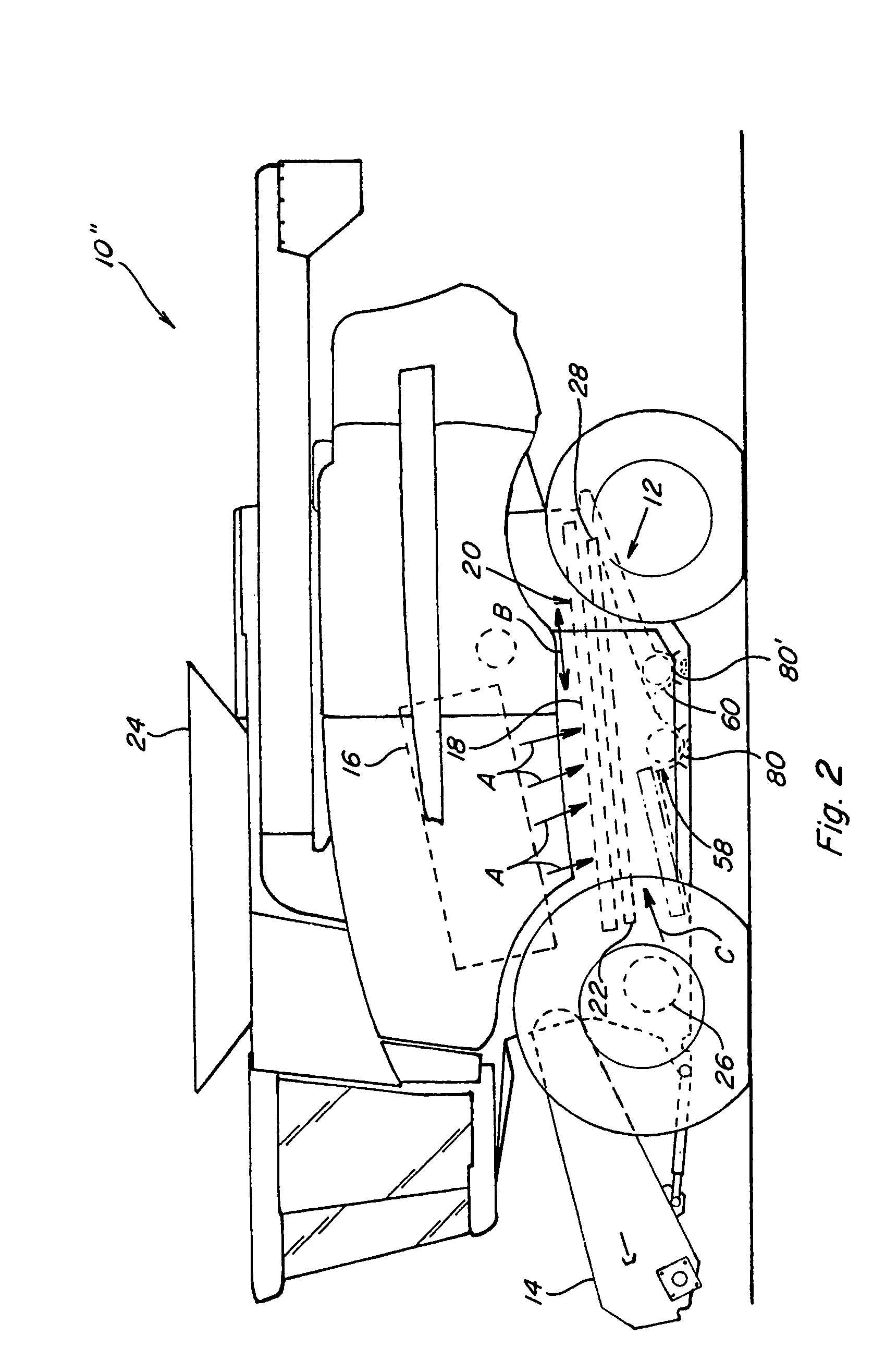
[0035]Referring now to the drawings, wherein like numbers refer to generally like items or features, FIGS. 1 and 2 depict generally similar agricultural combines 10 and 10″ that include similar, but somewhat different, respective clean grain and tailings conveying systems 12 and 12″, each of which conveying systems 12 and 12″ include clean grain auger trough and tailings auger trough constructions that have associated therewith auger trough clean-out doors according to the present invention.

[0036]Combines 10 and 10″ are of conventional, well known construction, each including a feeder house 14 on a front end thereof, to which is connectable a header (not shown), operable to sever a swath of crops from a field as the combine is moved forwardly thereover and to convey the severed crops to feeder house 14. Feeder house 14 includes an internal conveying system (not shown), for conveying the crops upwardly and rearwardly into the bodies of the combines 10 and 10″, into an inlet of a sepa...


PUM


Abstract

An auger trough and associated clean-out door construction of a clean grain and tailings conveying system for an agricultural combine, such construction including a pair of spaced, depending auger trough side walls that extend laterally across a combine between opposed sidesheets, with a removable door panel positionable across the combine between the opposed sidesheets and between said auger trough side walls to form an auger trough base, which door panel is configured to be so engageable with the auger trough side walls to substantially close the bottom of the auger trough and whose opposite ends are configured to be complementarily engageable with engagement features associated with the sidesheets to maintain such door panel in place during harvesting operations and, with such auger trough side walls, to define a generally rigid trough between the opposed sidesheets. Preferably, the door panel has a first end configured to be engageable with and to rest upon a projecting flange on a first of the opposite sidesheets and a second, latch end with an associated latch mechanism for engaging a complementary latching feature on the second, of the opposed sidesheets for generally securing the door panel in position as the bottom of the auger trough.

Description

TECHNICAL FIELD[0001]This invention relates generally to clean grain and tailings conveying systems of agricultural combines and to a construction for facilitating the clean out of the auger troughs of such systems, and, more particularly, to an auger trough and associated auger trough clean-out door for such systems.BACKGROUND ART[0002]In the harvesting of crops it is desired that the grain be separated from other elements or portions of the crop, such as from pod or cob fragments, straw, stalks, and the like. Agricultural combines typically have employed a rotary threshing or separating system for separating and segregating the grain from such other crop elements or portions. Typical of such rotary threshing or separating systems are constructions such as those described and depicted in Van Buskirk U.S. Pat. No. 3,537,460, issued to International Harvester Company, and Hall et al. U.S. Pat. No. 4,884,994, issued to Deere and Company. In general, rotary threshing or separating syst...

Claims


Application Information

Patent Timeline
Patent Type & Authority Patents(United States)
IPC IPC(8): A01B71/08
CPCA01F12/44
Inventor CLAERHOUT, BRYAN S.MATOUSEK, ROBERT A.
Owner BLUE LEAF I P INC
Learn More