
Coin discriminators

a coin and discriminator technology, applied in coin testing, paper-money testing devices, instruments, etc., can solve the problem of not being able to deal with bogus coins of similar metal content that are generally accurate, and achieve the effect of increasing the number of counterfeit coins that are rejected

Active Publication Date: 2009-09-08
SCAN COIN IND AB
View PDF53 Cites 15 Cited by
  • Summary
  • Abstract
  • Description
  • Claims
  • Application Information

AI Technical Summary

Problems solved by technology

The use of one or more recognition sets of parameters was proposed in GB 2135492A, each recognition set consisting of the highest and lowest values of the characteristic being measured, but this is not generally sufficiently accurate to deal with some bogus coins of a similar metal content.

Method used


Image

  • Coin discriminators
  • Coin discriminators
  • Coin discriminators

Examples


Embodiment Construction

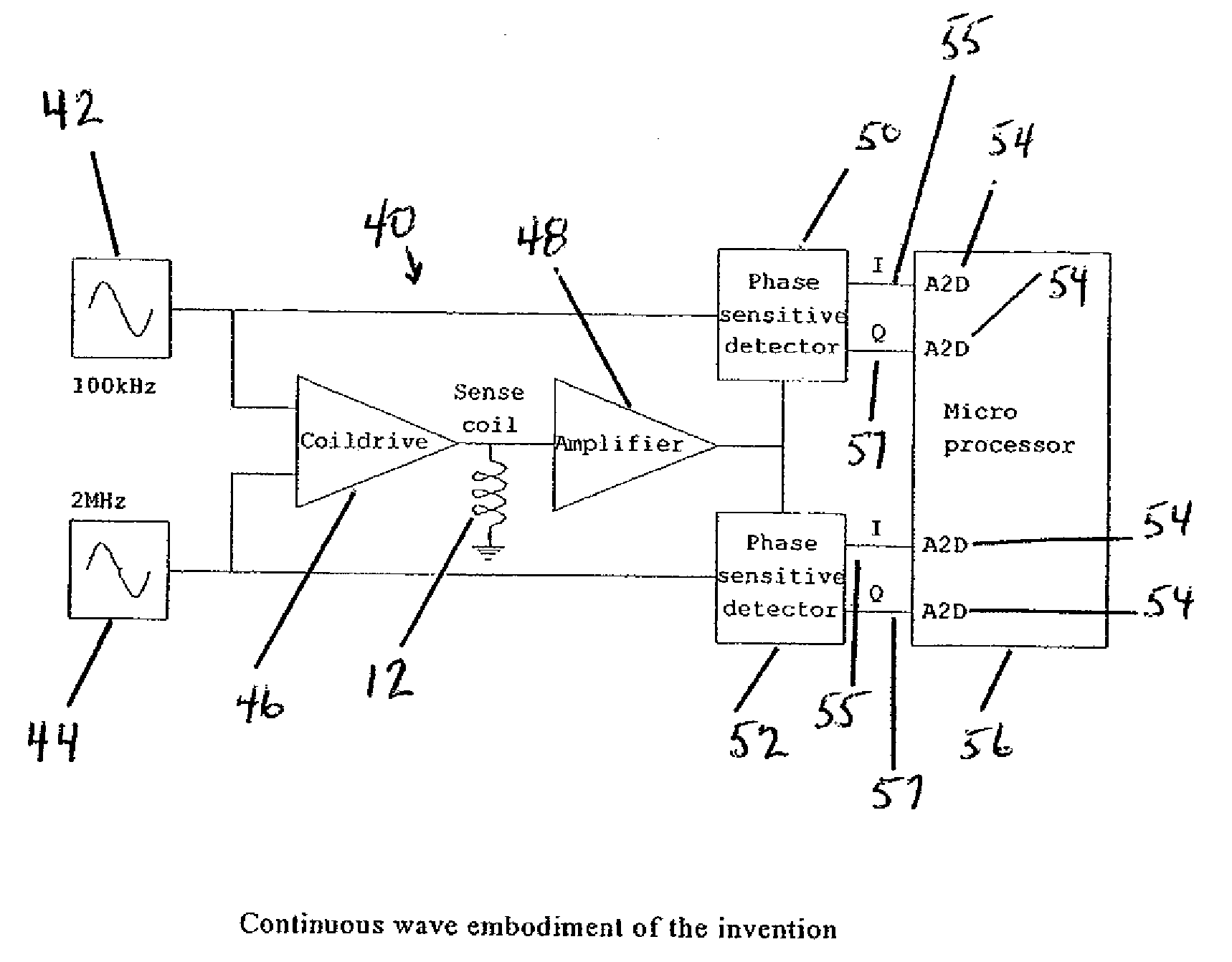
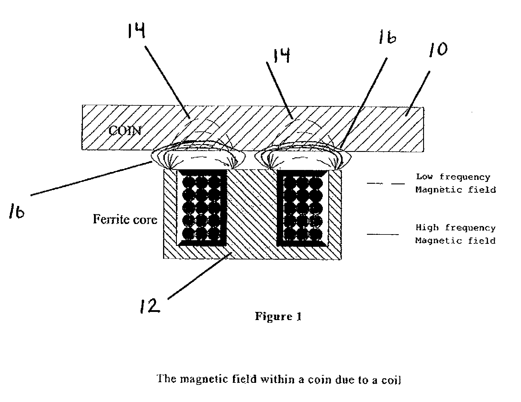
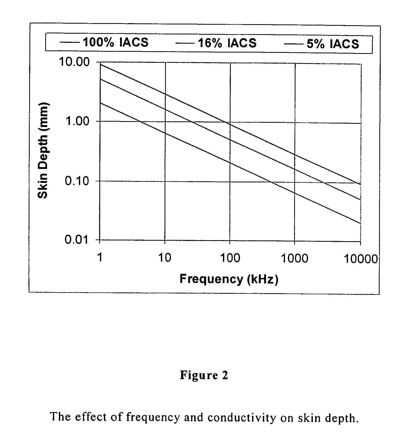
[0043]In one embodiment a single coil 12, such as the coil 12 of FIG. 1, is driven at two frequencies (e.g. a low frequency and a high frequency). The low frequency is chosen to develop a low frequency magnetic field 14 that penetrates to a skin depth of just less than 1 mm, a depth that is less than the thickness of coins 10 under test. The high frequency is chosen to develop a high frequency magnetic field 16 that penetrates to a skin depth of about 0.1 mm. The presence of a coin 10 causes the apparent inductance and resistance of the coil 12 to change. These changes are measured at both frequencies. From these changes the conductivity of the coin can be calculated. The high frequency change gives the surface conductivity and the low frequency gives the bulk conductivity.

[0044]If a large number of coins 10 are measured and the conductivities are plotted against each other a distribution 20 like the one shown in FIG. 3, is produced. The graph shows that coins 10 with a high surface...


PUM

PropertyMeasurementUnit
frequenciesaaaaaaaaaa
frequencyaaaaaaaaaa
frequencyaaaaaaaaaa

Abstract

A coin discriminator measures both the surface and average electrical conductivity of coins in order to distinguish genuine minted coins from fake or bogus coins such as cast coins which may be nominally of the same material as a minted coin. The conductivities are measured using a coil to induce eddy currents within the coin. The high frequency components of the eddy current are monitored to measure the surface conductivity. The low frequency components are measured to monitor the bulk or average conductivity.

Description

CROSS-REFERENCE TO RELATED APPLICATIONS[0001]This application is a continuation of application Ser. No. 10 / 948,708, filed on Sep. 23, 2004; now abandoned which application claims the benefit of provisional application No. 60 / 553,149, filed Mar. 15, 2004, and provisional application No. 60 / 553,220, filed Mar. 15, 2004, and which application also claims priority to British application no. GB0322354.2, filed Sep. 24, 2003, and British application no. GB0405616.4, filed Mar. 12, 2004.INCORPORATION BY REFERENCE[0002]The specification of U.S. application Ser. No. 10 / 948,708, filed on Sep. 23, 2004; provisional application No. 60 / 553,149, filed Mar. 15, 2004; provisional application No. 60 / 553,220, filed Mar. 15, 2004; British application no. GB0322354.2, filed Sep. 24, 2003; and British application no. GB0405616.4, filed Mar. 12, 2004 are incorporated herein in their entirety, by this reference.TECHNICAL FIELD[0003]The present invention relates to a coin discriminator and to a method of d...

Claims


Application Information

Patent Timeline
Patent Type & Authority Patents(United States)
IPC IPC(8): G07D5/08
CPCG07D5/08G07D5/02
Inventor HOWELLS, GEOFFREY
Owner SCAN COIN IND AB
Learn More