
Graphical user interface for 3-D in-vivo imaging

a user interface and in-vivo imaging technology, applied in the field of user interface software, can solve the problems of increasing complexity of in-vivo imaging applications, affecting the use of researchers' data sets, and a large number of analytical processes a researcher may perform on a data set, so as to achieve the effect of easy viewing and analysis

Inactive Publication Date: 2009-08-25
XENOGEN CORP
View PDF32 Cites 73 Cited by
  • Summary
  • Abstract
  • Description
  • Claims
  • Application Information

AI Technical Summary

Benefits of technology

"The present invention provides a computer system and user interface that allow users to view and analyze two-dimensional and three-dimensional in vivo images and imaging data. The user interface is well-suited for various operations related to in vivo light imaging such as investigation and control of tomographic and topographic algorithms, control of spectral imaging and analysis, and comparison of two-dimensional or three-dimensional imaging data obtained at different times. The computer system includes one or more processors, memory, and a display capable of displaying the image and associated information in a flexible and comfortable way. The image comprises a three-dimensional representation of an object surface superimposed with a three-dimensional light emitting representation, which includes information describing a location and magnitude of electro-magnetic radiation or light emitted from within the object. The computer system further comprises one or more reconstruction tools that allow users to reconstruct the three-dimensional light emitting representation of the object. The invention provides a convenient and efficient tool for analyzing and evaluating in vivo images."

Problems solved by technology

Specialized in-vivo imaging applications can present particular challenges to the design of an appropriate user interface.
In-vivo imaging applications are increasing in complexity and often provide copious amounts of information.
The large number of analytical processes a researcher may perform on a data set also complicates usage.
The excessive amount of data coupled with the large number of analytical processes inhibits design of an easy to manage user interface.
Currently, users lack an environment that fully services user needs and permits convenient management of the large amount of data and analytical processes associated with conventional imaging.

Method used


Image

  • Graphical user interface for 3-D in-vivo imaging
  • Graphical user interface for 3-D in-vivo imaging
  • Graphical user interface for 3-D in-vivo imaging

Examples


Embodiment Construction

[0034]The present invention will now be described in detail with reference to a few preferred embodiments thereof as illustrated in the accompanying drawings. In the following description, numerous specific details are set forth in order to provide a thorough understanding of the present invention. It will be apparent, however, to one skilled in the art, that the present invention may be practiced without some or all of these specific details. In other instances, well known process steps and / or structures have not been described in detail in order to not unnecessarily obscure the present invention.

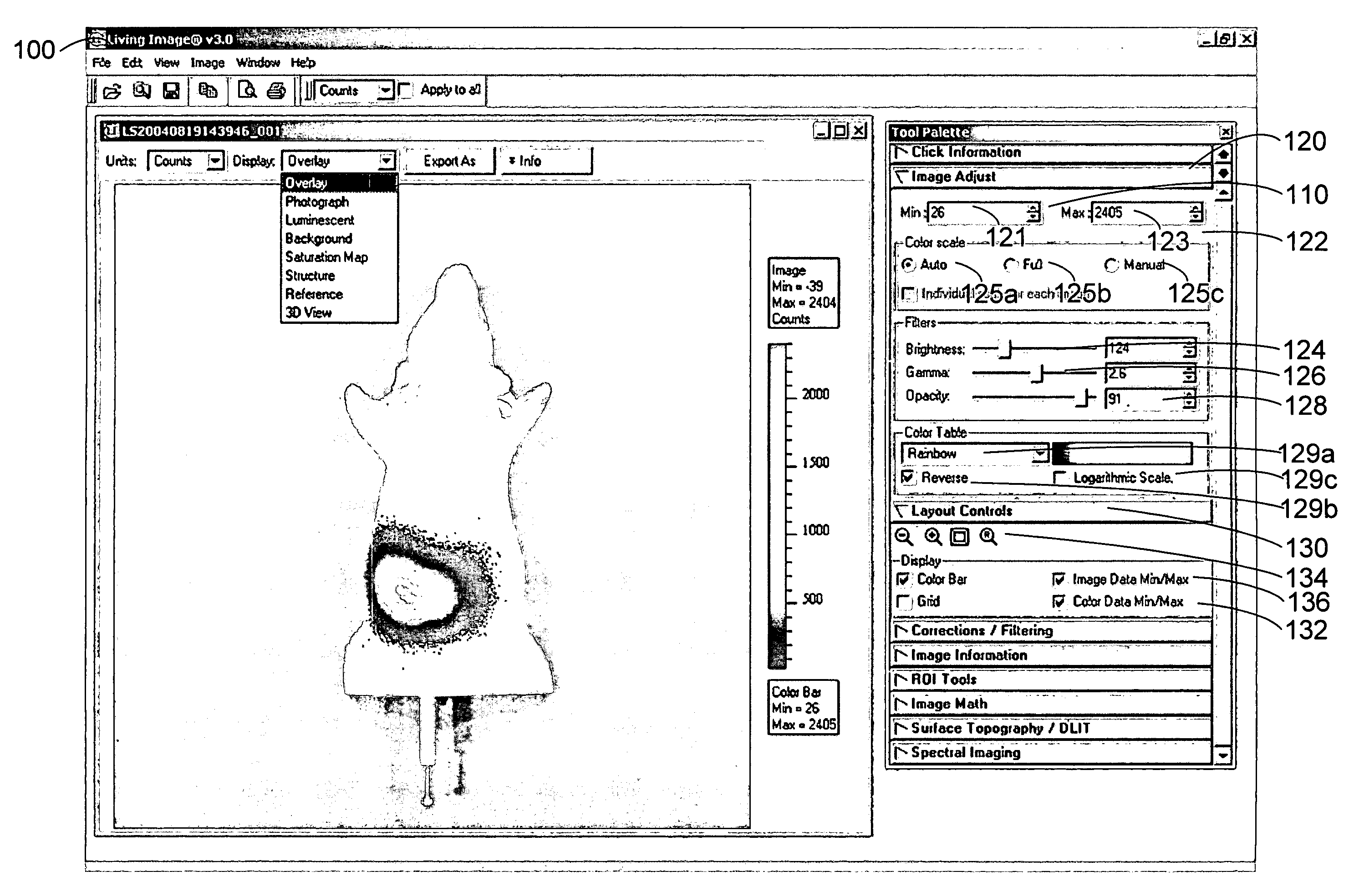
[0035]A graphical user interface (GUI) is provided which allows a user to perform numerous operations suitable for image analysis for an in-vivo imaging application. Using a GUI of this invention, the user may create and manipulate analysis tools and perform a wide variety of measurements on complex images (such as three-dimensional reconstructed in-vivo images of an internal light source)...


PUM


Abstract

The present invention provides a computer system and user interface that allows a user to readily view and analyze two-dimensional and three-dimensional in vivo images and imaging data. The user interface is well-suited for one or more of the following actions pertinent to in vivo light imaging: investigation and control of three-dimensional imaging data and reconstruction algorithms; control of topographic reconstruction algorithms; tomographic spectral imaging and analysis; and comparison of two-dimensional or three-dimensional imaging data obtained at different times.

Description

CROSS-REFERENCE TO RELATED APPLICATION[0001]This application is a continuation-in-part of U.S. Patent Application entitled “GRAPHICAL USER INTERFACE FOR IN-VIVO IMAGING”, filed on Jun. 9, 2003 (U.S. application Ser. No. 10 / 458,579) now U.S. Pat. No. 7,299,422, which is incorporated by reference herein in its entirety for all purposes and which was a continuation application of U.S. patent application Ser. No. 09 / 439,381, now U.S. Pat. No. 6,614,452 entitled “GRAPHICAL USER INTERFACE FOR IN-VIVO IMAGING”, filed on Nov. 15, 1999, from which priority is also claimed and which is hereby incorporated by reference in its entirety for all purposes.FIELD OF THE INVENTION[0002]This invention relates generally to user interface software running on a computer. More particularly, the present invention relates to user interface software useful in examining and analyzing three-dimensional in-vivo images.BACKGROUND OF THE INVENTION[0003]In a computer application, there are numerous ways to present...

Claims


Application Information

Patent Timeline
Patent Type & Authority Patents(United States)
IPC IPC(8): G06F3/00G06K9/36G06F3/033G06F3/048
CPCA61B5/0059A61B5/7435G06F3/04815G06F3/0481A61B2503/40A61B5/00
Inventor RICE, BRADLEY W.CABLE, MICHAEL D.MIRVAR, BINOYCOQUOZ, OLIVIERKUO, CHAINCY
Owner XENOGEN CORP
Learn More