
Acoustic signal coding method and apparatus, acoustic signal decoding method and apparatus, and acoustic signal recording medium

Inactive Publication Date: 2009-08-25
SONY CORP
View PDF17 Cites 33 Cited by
  • Summary
  • Abstract
  • Description
  • Claims
  • Application Information

AI Technical Summary

Benefits of technology

[0057]According to the present invention having been summarized in the above, a phenomenon that a frequency component developed for a specific limited time is diffused in a frame can be inhibited by dividing an acoustic time domain signal into a plurality of bands for analysis, detecting the time domain signal of the frequency component developed in the specific limited time and process the amplitude information of the time domain signal with a high accuracy, and thus the frequency resolution can be improved for an improved coding efficiency.

Problems solved by technology

Since no masking effect is utilized in this method, however, no optimum acoustic noise reduction can practically be attained.
However, even when a sine wave input is used in this method to measure a signal-to-noise ratio, not so good a signal-to-noise ratio can be assured since the bit allocation is fixed.
If a signal is decomposed into frequency components once and the frequency components are quantized for coding, a wave signal obtained by decoding and combining the frequency components will incur a quantum noise.
However, if the frequency components of the original vary rapidly, the quantum noise in the wave signal will be large even in a portion where the original signal waveform is not large and the quantum noise called “pre / post echo” will not be masked by a simultaneous masking.
Thus the quantum noise will be an acoustic disturbance.
Especially when a signal is decomposed into many frequency components using the spectrum transform, the time resolution will be worse and thus a large quantum noise will occur for a long period.
In this case, reduction of the transformed length of spectrum will shorten also the period for which the quantum noise takes place, which however will make worse the frequency resolution.
However, since the transformed length reduction will cause to decrease the number of bits per transformed block, no sufficient accuracy of quantization can be assured so that no good sound quality of the decoded signal can be provided.
In addition to the pre and / or post echo, however, there are other factors to disturb the auditory sensation.
Among others, setting a frame length a little larger in the transform coding will be an acoustic disturbance.
This phenomenon will take place also when an original acoustic time domain signal does not vary greatly in a block, which problem could not be solved by any apparatus adapted to suppress a pre and / or post echo.

Method used


Image

  • Acoustic signal coding method and apparatus, acoustic signal decoding method and apparatus, and acoustic signal recording medium
  • Acoustic signal coding method and apparatus, acoustic signal decoding method and apparatus, and acoustic signal recording medium
  • Acoustic signal coding method and apparatus, acoustic signal decoding method and apparatus, and acoustic signal recording medium

Examples


Embodiment Construction

[0097]The embodiments of the present invention which will be described herebelow include an acoustic signal coding method and apparatus adapted to transform an acoustic signal such as an audio and / or speech signal to a spectrum, and then code it to generate a code row, an acoustic signal decoding method and apparatus adapted to decompose a code row, decode and reconstruct it to a spectrum, and then inversely transform it to an acoustic signal, an acoustic signal coder and / or decoder (will be referred to as “CODEC” hereinafter), and recording media having recorded therein procedures of coding and decoding an acoustic signal, etc.

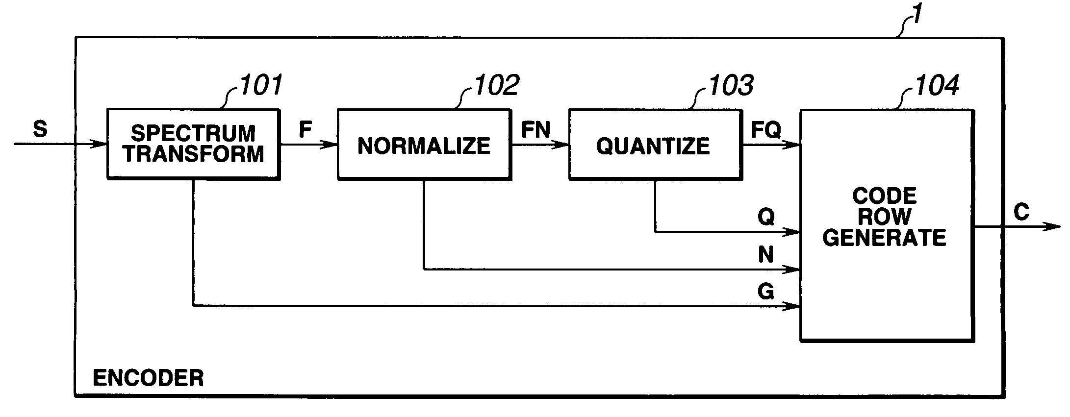
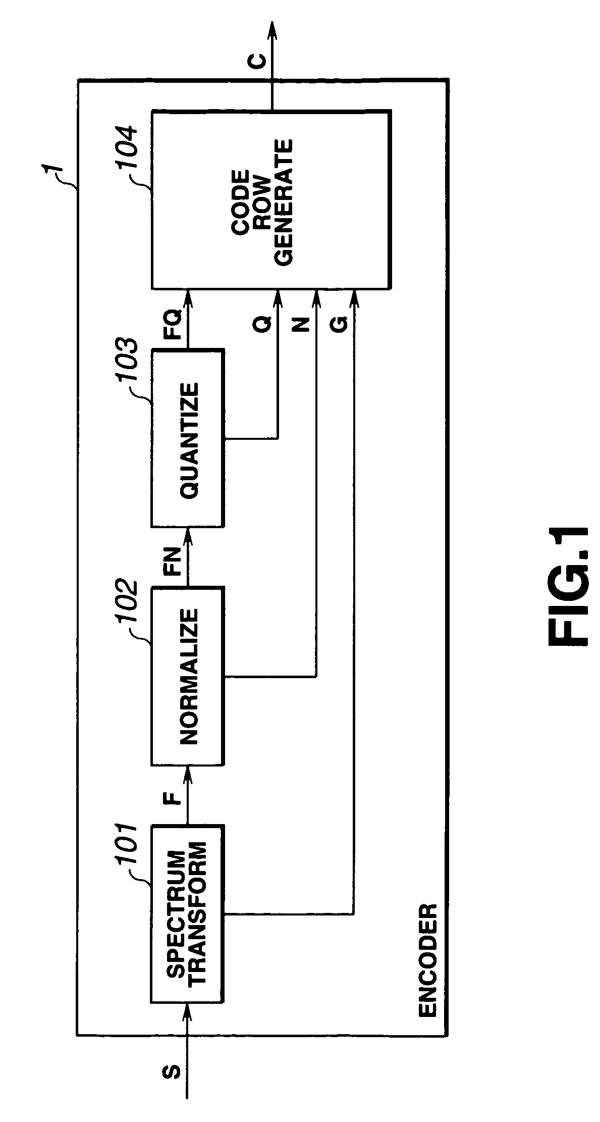
[0098]Referring now to FIG. 1, there is illustrated in the form of a schematic block diagram an embodiment of the acoustic signal encoder according to the present invention. The acoustic signal encoder is generally indicated with a reference 1.

[0099]The acoustic signal encoder 1 comprises a spectrum transformation circuit 101 to process the amplitude of a tim...


PUM


Abstract

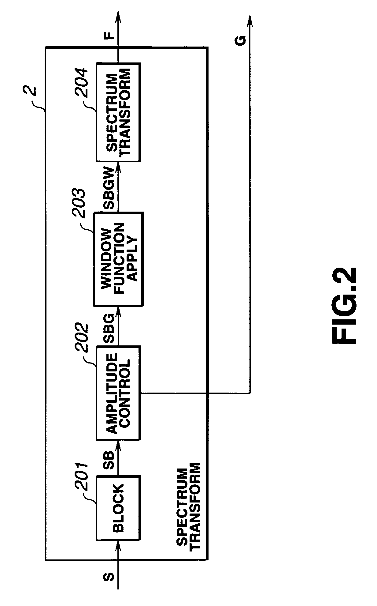
Acoustic signal encoder is provided which comprises a subband filter band to divide an original signal into a plurality of frequency bands, a spectrum transformation circuit to detect the amplitude of a signal in each of the plurality of frequency bands in each of sub-blocks resulted by division of a block length for signal coding, process the signal amplitude in each band based on the detected amplitude and transform the signals divided in the frequency bans to spectra, a normalizing circuit and quantizing circuit to normalize and quantize the spectrum, respectively, and a code row generator to generate a code row from the signals processed by the above circuits.

Description

PRIORITY CLAIM[0001]The present application claims priority from Japanese Application No. 10-285624, filed on Oct. 7, 1998, which is hereby incorporated by reference.BACKGROUND OF THE INVENTION[0002]1. Field of the Invention[0003]The present invention relates to an acoustic signal coding method and apparatus, acoustic signal decoding method and apparatus, and a recording medium having recorded therein programs for the coding and decoding.[0004]2. Description of the Related Art[0005]There have been proposed various methods for highly efficient coding of audio or speech signal, such as a non-blocked frequency band division method called “SBC (subband coding)” in which an audio signal or the like on the time base is coded by dividing the signal into a plurality of frequency bands without blocking it, a blocked frequency band division method called “transform coding” in which a signal on the time base is transformed to a signal on the frequency base (spectrum transform) to divide it int...

Claims


Application Information

Patent Timeline
IPC IPC(8): G06F21/00G10L19/00G10L19/02G10L19/022G10L19/035H03M7/30H04B14/00
CPCG10L19/0204G10L19/032G10L19/022
Inventor SUZUKI, SHIRO
Owner SONY CORP
Learn More