
Method and apparatus for generating electric power

a technology of electric power generation and method, applied in the field of electric generation systems, can solve the problems of reducing fuel efficiency, reducing the overall construction and operating cost of the marine vessel, and limiting the size/weight of the known transformer

Inactive Publication Date: 2009-08-18
GENERAL ELECTRIC CO
View PDF60 Cites 27 Cited by
  • Summary
  • Abstract
  • Description
  • Claims
  • Application Information

AI Technical Summary

Benefits of technology

"The patent describes a method and system for generating and distributing electric power. The system includes an open-winding generator and electric power electronics apparatuses that are connected to a bus. The system can be used in a marine vessel with an electric propulsion motor. The technical effect of this patent is to provide a more efficient and flexible way to generate and distribute electric power in a marine vessel."

Problems solved by technology

While transformers are acceptable for reducing the output voltage from the generator to a lower voltage that is utilized by the various equipment coupled to the bus, known transformers have size / weight constraints.
Specifically, marine vessels that include a wide variety of loads, also may require a large quantity of transformers to provide the necessary voltage levels required by the loads.
As a result, the combined weight of the transformers increases the overall weight of the marine vessels, thus reducing fuel efficiency and increasing the overall construction and operating costs of the marine vessel.
Moreover, transformers utilized with relatively large electric equipment may have a relatively large footprint which may be difficult to accommodate within the limited confines of a marine vessel.

Method used


Image

  • Method and apparatus for generating electric power
  • Method and apparatus for generating electric power
  • Method and apparatus for generating electric power

Examples


Embodiment Construction

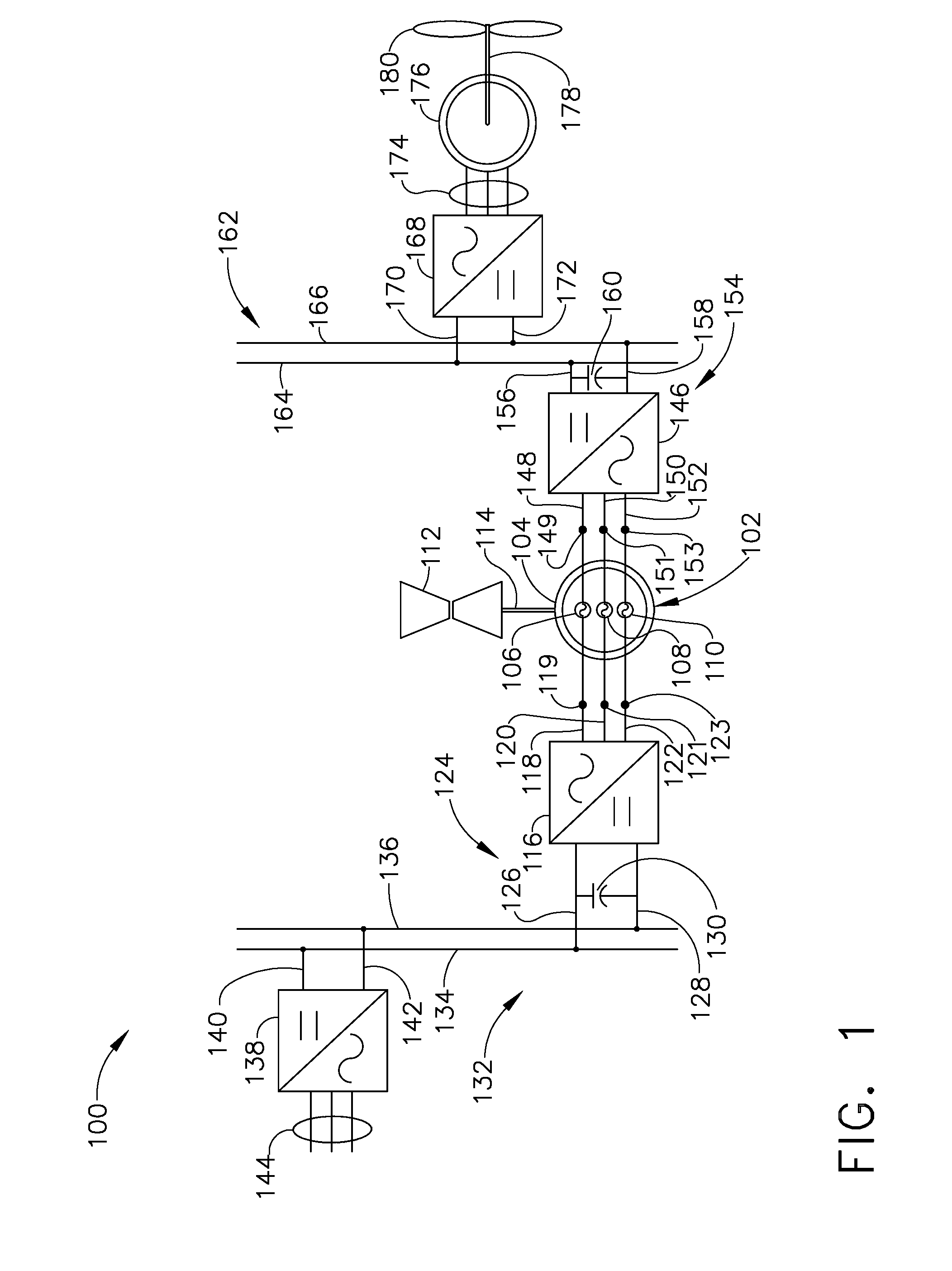
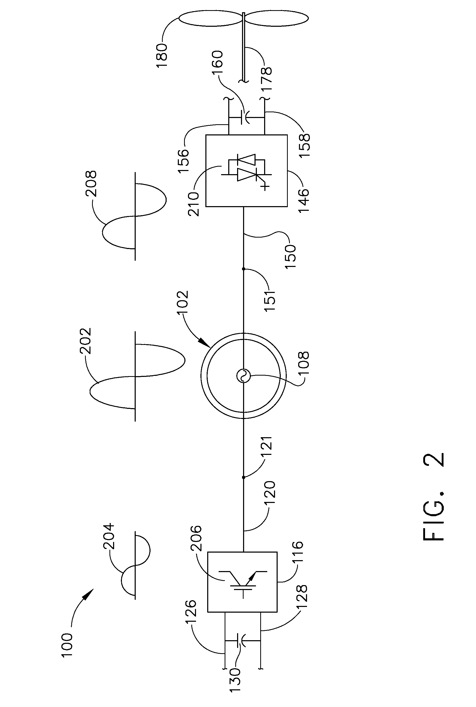
[0019]FIG. 1 is a schematic view of a portion of an exemplary marine vessel electric power generation and distribution system 100. System 100 includes an open-winding generator 102, wherein such generators typically include both of the associated terminals for each generator phase winding being brought out for connection to external buses. This is in contrast to many known generators wherein one end of each of the A-phase lead, the B-phase lead, and the C-phase lead are electrically coupled to form a stator configuration generally known as a delta- (or Δ-) wound machine or a wye- (or Y-) wound machine.

[0020]In the exemplary embodiment, generator 102 is a synchronous, three-phase, wound rotor, 36 megawatt (MW), 6600 volts alternating current (VAC), two-pole, 6000 revolutions per minute (RPM) generator that includes a rotor (not shown) and a stator 104. Alternatively, generator 102 is any type of generator including, but not limited to, salient pole generators, double-sided stator gen...


PUM


Abstract

A method of generating electric power includes providing at least one open-winding generator having at least one winding, wherein the at least one winding has a first terminal and a second terminal. The method also includes electrically coupling the first terminal to a first electric power electronics apparatus via a first electric bus and electrically coupling the second electric terminal to a second electric power electronics apparatus via a second electric bus. The method further includes inducing and regulating a first voltage on the first electric bus and inducing and regulating a second voltage on the second electric bus.

Description

BACKGROUND OF THE INVENTION[0001]This invention relates generally to electric generation systems, and more particularly to an electric generation system that includes a combination of generators and converters that are configured to derive multiple voltages without the use of transformers.[0002]At least one known marine vessel includes a generator that is utilized to provide power to an electric distribution system. The electric distribution system includes a plurality of loads which receive power from the buses. To provide power to the loads, known electric distribution systems include a plurality of transformers that are utilized to reduce the voltage level supplied from the generator to a voltage level that is required to operate the loads. For example, at least some marine loads such as the propulsion system are fed at a medium voltage that is between approximately 2.3 kiloVolts (kV) and approximately 13.8 kV, while auxiliary loads, often referred to as hotel or ship service loa...

Claims


Application Information

Patent Timeline
Patent Type & Authority Patents(United States)
IPC IPC(8): F02D29/06H02P9/04F03D9/00H02H7/06H02K17/44H02K19/38H02K47/00H02K7/20H02P11/00H02P9/00
CPCB60L11/08B63J3/00H02J4/00B60L2200/32Y02T10/70Y02T90/38Y02T10/7077B63J2003/002B60L50/13H02J2310/42Y02T10/7072Y02T90/40B63J3/02H02J3/36H02M5/4585
Inventor RAJU, RAVISEKHAR NADIMPALLI
Owner GENERAL ELECTRIC CO
Learn More