
Methods and apparatus for controlling windfarms and windfarms controlled thereby

a technology of windfarms and wind farms, applied in the direction of active/predictive/anticipative control, electric generator control, machines/engines, etc., can solve the problems of electrical equipment breaking down and sparking, circuit breakers to trip, and components to overhea

Active Publication Date: 2009-08-11
GE INFRASTRUCTURE TECH INT LLC
View PDF14 Cites 15 Cited by
  • Summary
  • Abstract
  • Description
  • Claims
  • Application Information

AI Technical Summary

Benefits of technology

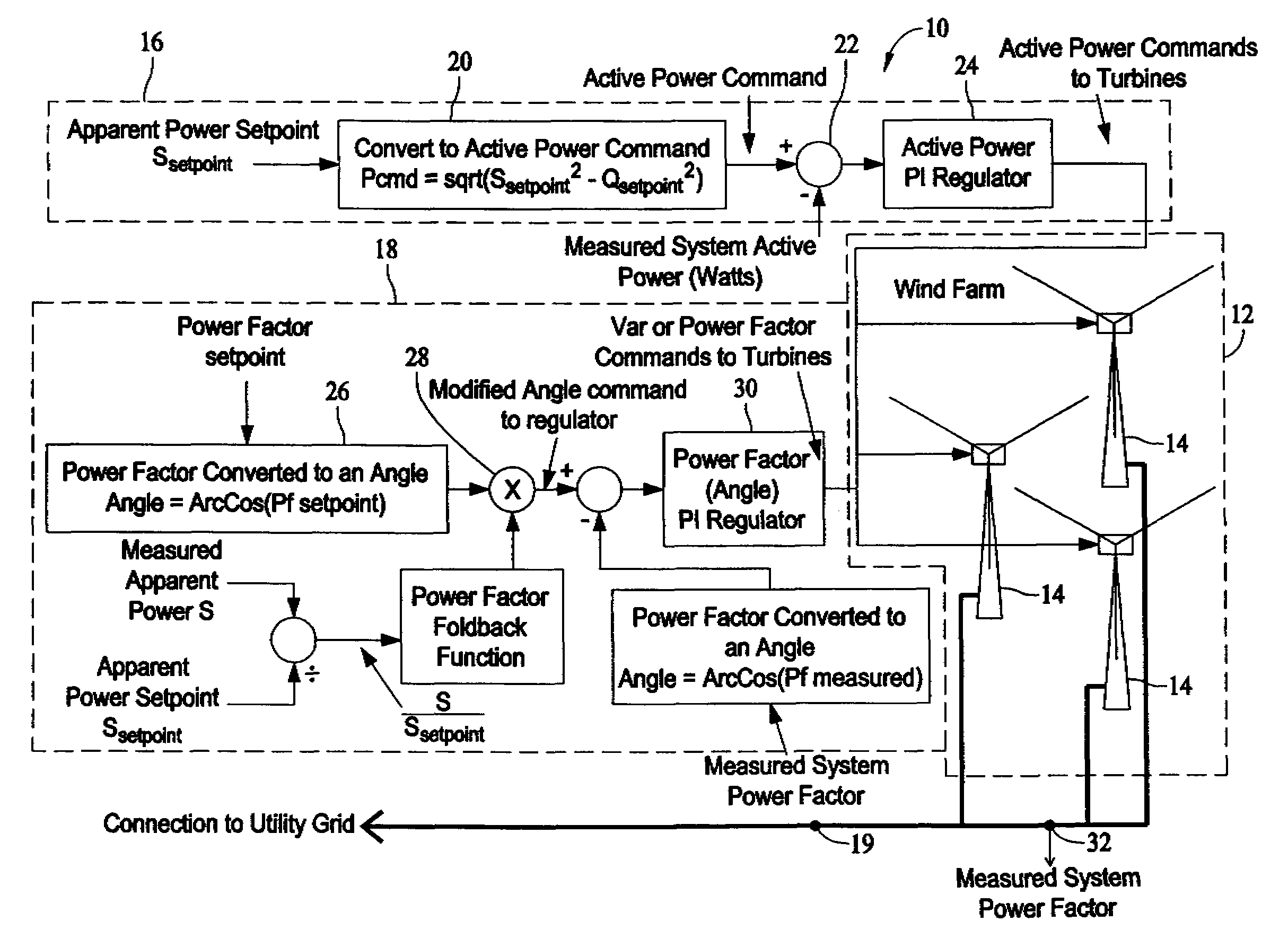
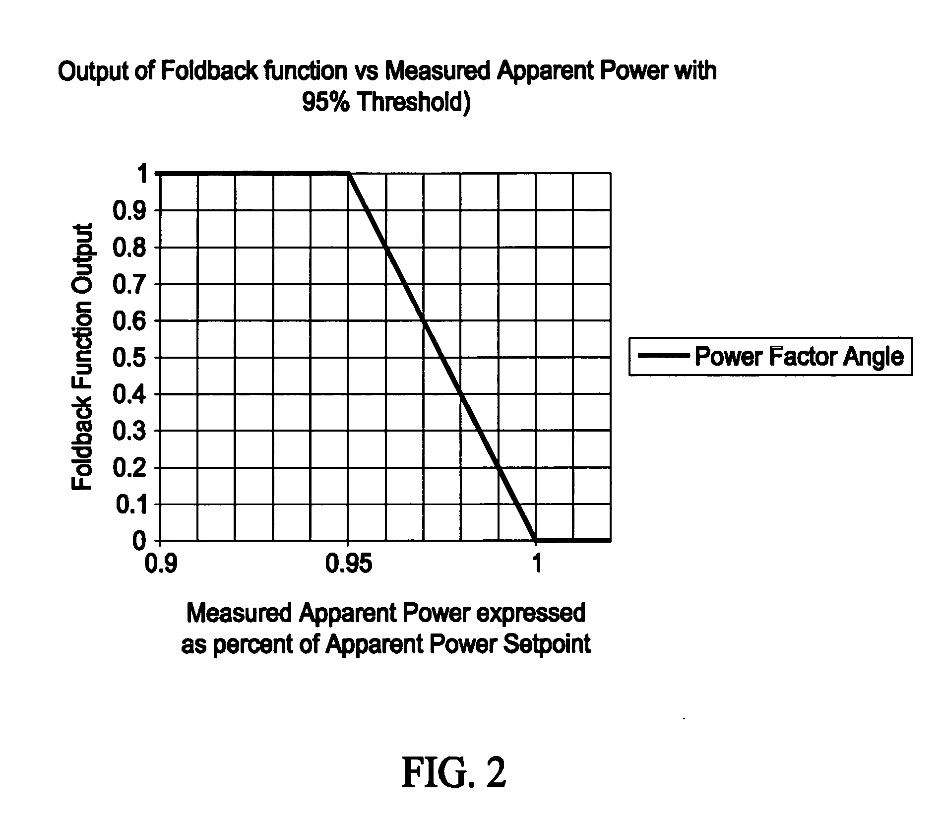
The present invention provides a method, apparatus, and regulated windfarm for controlling power produced by wind turbines. The method includes regulating active power and power factor of the windfarm in accordance with an apparent power setpoint and a power factor setpoint, respectively. During periods in which the apparent power setpoint is approaching or exceeded, the method reduces the power factor setpoint angle magnitude and regulates the power factor of the windfarm in accordance with the reduced power factor setpoint angle magnitude. This allows for increased or maximum active power production during periods of high wind and seamless transfer to the correct power factor during periods of lower winds.

Problems solved by technology

It is often necessary to limit the amperage being sent onto a transmission line, because it is this quantity that results in the heating of components or of the transmission line itself and that causes circuit breakers to trip.
If the rated voltage is exceeded, the electrical equipment will break down and spark.
If the rated amperage is exceeded, the component will overheat.

Method used


Image

  • Methods and apparatus for controlling windfarms and windfarms controlled thereby
  • Methods and apparatus for controlling windfarms and windfarms controlled thereby
  • Methods and apparatus for controlling windfarms and windfarms controlled thereby

Examples


Embodiment Construction

[0011]As used herein, all signals that relate to values or measurements in a system are considered as “signals indicative of” the values or measurements. Such signals can be scaled, offset, or mapped in an appropriate manner as a design choice to facilitate circuit design. A “signal indicative of” a value or measurement can be, for example, an analog voltage from a control or measuring device or a digital value stored in a memory or measured using a digital measuring instrument. Unless otherwise noted, such a signal can include a scaling factor, an offset, or another mapping as a design choice to facilitate the implementation of functional blocks of circuitry described herein.

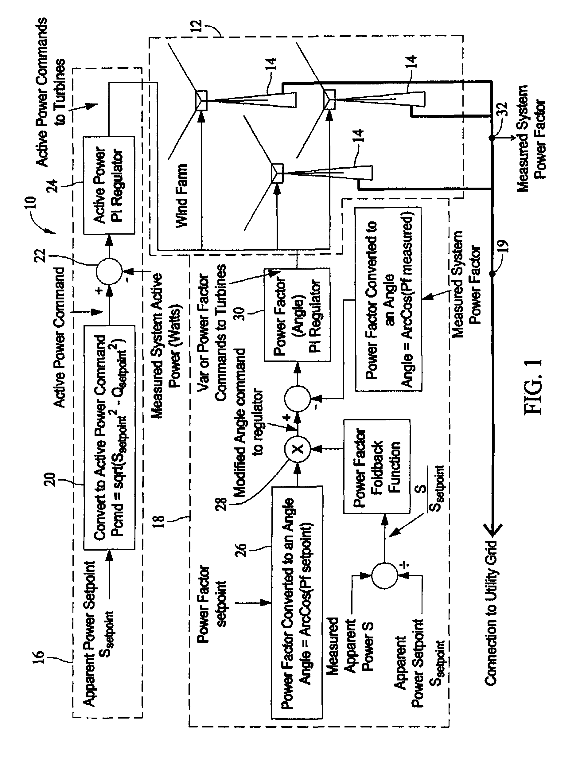
[0012]In some configurations of the present invention and referring to FIG. 1, a windfarm control system 10 for a windfarm 12 comprising one or more wind turbines 14 includes an apparent power control loop 16 and a power factor control loop 18. Apparent power control loop 16 regulates active power of windfarm 1...


PUM


Abstract

A method for controlling power produced by a windfarm includes regulating active power produced by the windfarm in accordance with an apparent power setpoint, and regulating a power factor of the windfarm in accordance with a power factor setpoint. However, during periods in which the apparent power setpoint is approached or exceeded, the method includes reducing a magnitude of an angle of a power factor setpoint towards zero and regulating the power factor of the windfarm in accordance with the reduced power factor setpoint angle magnitude.

Description

BACKGROUND OF THE INVENTION[0001]This invention relates generally to wind turbine energy generation systems and more particularly to methods and apparatus for controlling power generated therefrom and to the wind turbine energy generation systems controlled by such methods and apparatus.[0002]It is a common desire to regulate and / or limit apparent power in wind power plants (hereinafter referred to as “windfarms”). Otherwise, the power generated from the windfarm will vary with the power captured by the blades of each turbine, and that power varies with and the captured power is highly dependent upon instantaneous wind speed. Power can be regulated by, for example, pitching the blades of the wind turbines or rotating the axis of the rotor away from the direction of the wind.[0003]The output of a wind farm can be characterized, at least in part, by an apparent power. The apparent power is the sum of the actual, real power, measured in watts and dissipated through a resistive load, an...

Claims


Application Information

Patent Timeline
Patent Type & Authority Patents(United States)
IPC IPC(8): H02J3/46H02P9/00
CPCF03D7/028F03D7/048Y02E10/723F05B2270/708F05B2270/404Y02E10/72
Inventor CARDINAL, MARK EDWARDGANDHI, JIGNESH GOVINDLALKIRCHNER, ANDREASBRUGGER, REINHARD
Owner GE INFRASTRUCTURE TECH INT LLC
Learn More