Timepiece

a technology of timepieces and rotating stops, applied in the field of timepieces, can solve the problems of increasing the size of the timepiece, increasing the risk of false operation, and high fear, and achieve the effects of reducing false operation, reducing fear, and reducing false operation

Active Publication Date: 2009-08-11
SEIKO INSTR INC
View PDF10 Cites 17 Cited by
  • Summary
  • Abstract
  • Description
  • Claims
  • Application Information

AI Technical Summary

Benefits of technology

[0010]It is an aspect of the present invention to provide a timepiece in which operations for a rotation stop of the bezel and its release are easy, and reliability and a durability of the rotation stop are high.

Problems solved by technology

In the prior art, by a frictional force between the threaded ring and the bezel lower face and a frictional force between the both regulation protrusions of the case band and the bezel, since the bezel is fixed so as not to rotate, it is unavoidable that, just before this fixation completes, a rotation operation force of the threaded ring is exerted on the bezel and this becomes gradually large.
By this, such a fear is high that the bezel is rotated in conjunction with the threaded ring which is rotation-operated, and deviates from a desired position.
Additionally, in the prior art, since the threaded ring is rotation-operated, not only it is inconvenient in the operation, and, since the user judges the fact that the bezel became a fixed state by the fact that the rotation operation of the treaded ring became heavy, this judgment is liable to disperse.
By this, there is a possibility that an excess or deficiency occurs in the fixation of the bezel, and also a possibility that the threaded ring loosens is high.

Method used


Image

  • Timepiece
  • Timepiece
  • Timepiece

Examples


first embodiment

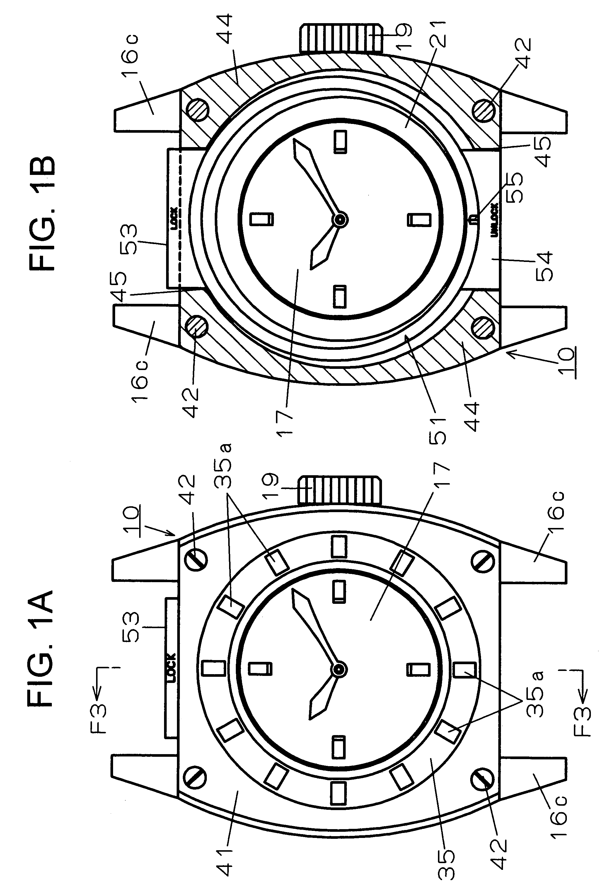
[0051]By referring to FIG. 1-FIG. 7, there is explained the present invention.

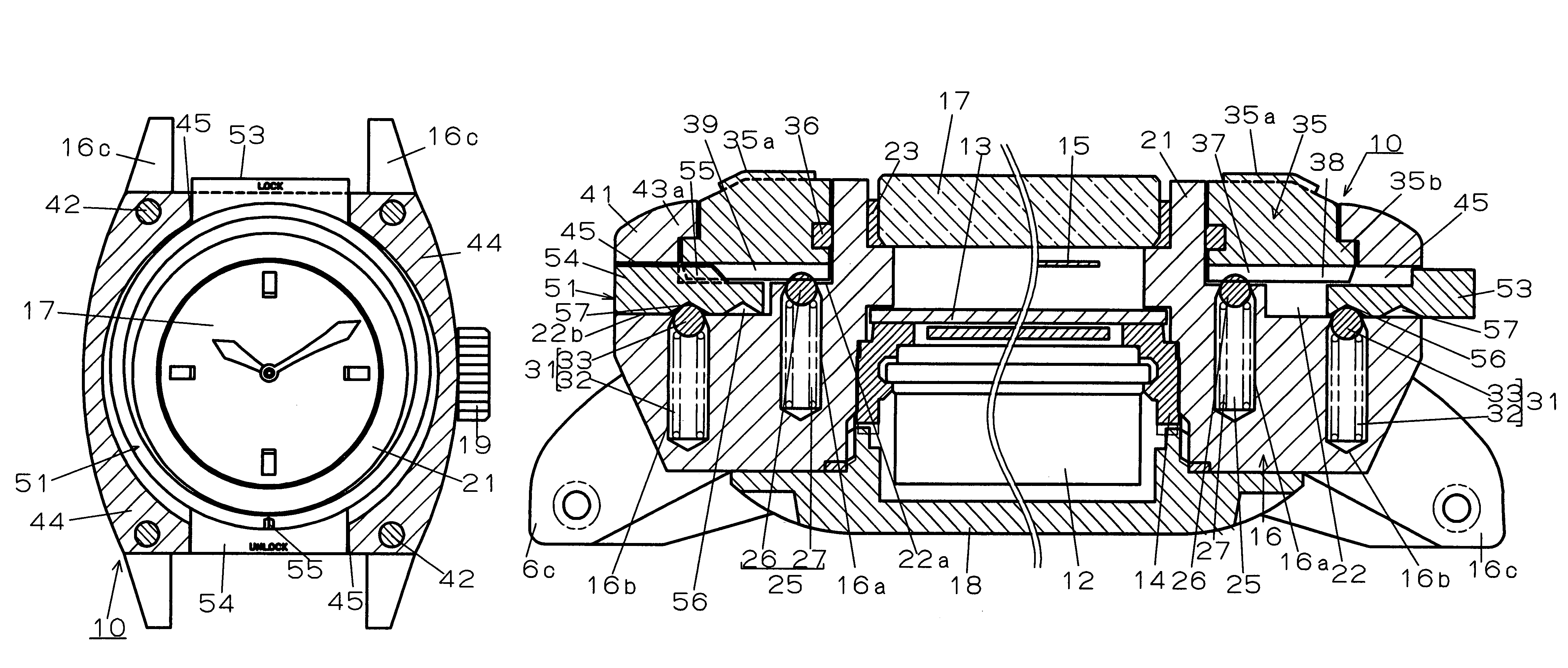
[0052]In FIG. 1-FIG. 4, a reference numeral 10 shows a watch, e.g., wristwatch. As shown in FIG. 3 and FIG. 4, in a timepiece armor assembly that this wristwatch 10 possesses, there are accommodated a timepiece movement 12, a dial 13, a casing ring 14, and the like. The dial 13 is attached to the timepiece movement 12. The timepiece movement 12 drives a display hand 15 opposing to the dial 13. The casing ring 14 supports the timepiece movement 12 to the timepiece armor assembly.

[0053]As shown in FIG. 3 and FIG. 4, the timepiece armor assembly possesses a case band 16, a cover glass 17, and a case back 18. The case band 16 is like an annulus, and desirably made of a metal. The cover glass 17 is fluid-tightly mounted while closing an opening in one face (front face) side in a thickness direction of the case band 16. The dial 13 and the display hand 15 are viewable through this cover glass 17. The case back 1...

second embodiment

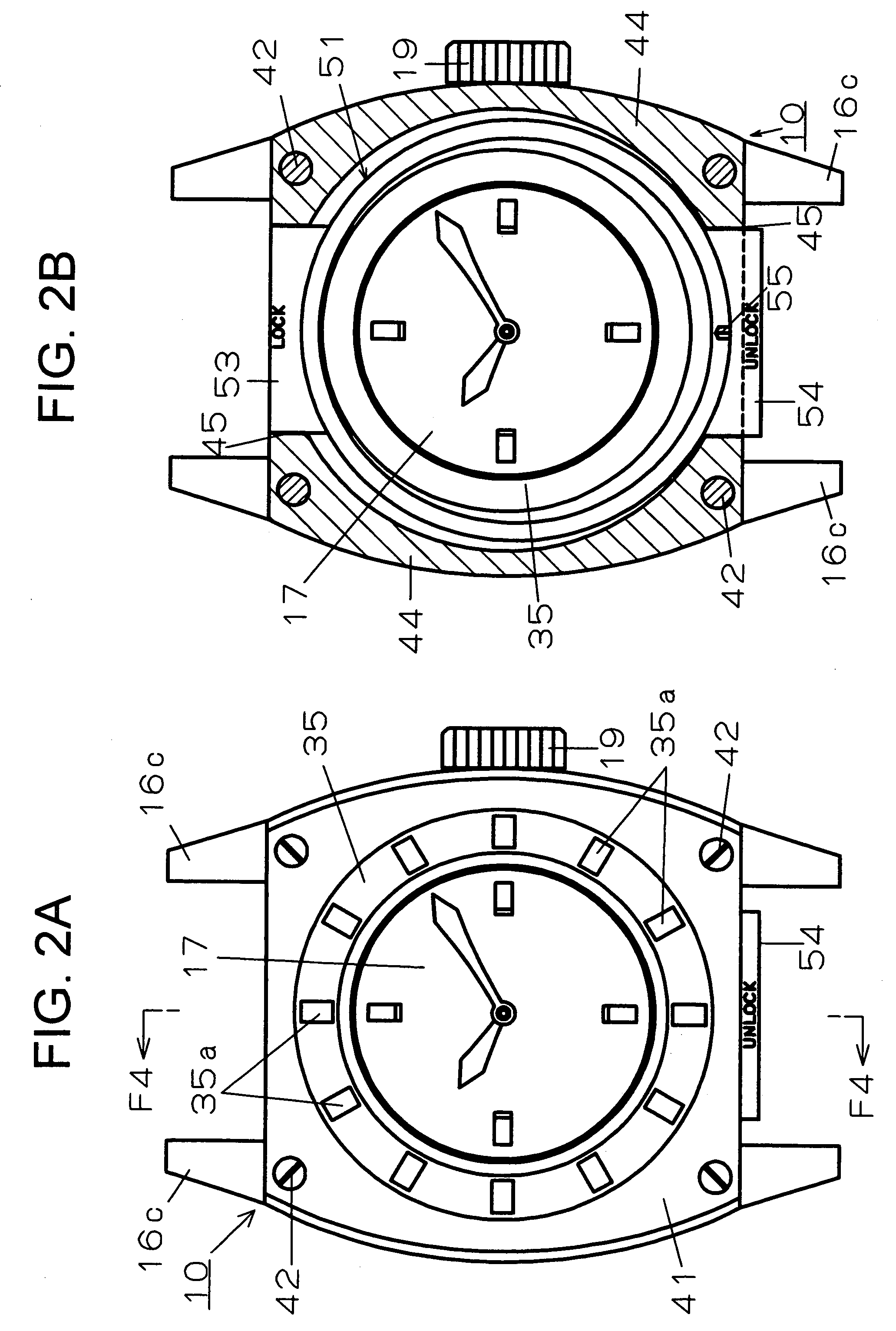
[0104]FIG. 8-FIG. 11 show the present invention. This second embodiment is the same as the first embodiment except matters explained below. Therefore, about the same constitution as the first embodiment, there is applied the same reference numeral as the first embodiment, thereby omitting its explanation together with its action, and hereunder there are explained the matters different from the first embodiment.

[0105]In the second embodiment, back face cover parts 16d, 16e are monolithically provided in each of, e.g., the 12 o'clock side and the 6 o'clock side of the case band 16. These back face cover parts 16d, 16e extend along a direction perpendicularly intersecting with a straight line connecting the operation convex parts 53, 54 of the lock member 51, concretely the 9 o'clock-3 o'clock direction of the wristwatch 10 as shown in FIG. 8 and FIG. 9.

[0106]As shown in FIG. 10, the back face cover part 16d is provided so as to cover the back face, of the operation convex part 53 in t...


PUM


Abstract

To provide a timepiece in which operations for a rotation stop of a bezel and its release are easy, and reliability and a durability of the rotation stop are high. A bezel is disposed in a bezel disposition part of a case band so as to be capable of rotation-operating, and positioning parts and lock parts, which comprise plural concave-convex portions juxtaposed in a direction of the rotation, are formed in a back face of the bezel. To the case band, there is attached a clip stop mechanism (positioning means), which permits clockwise and counterclockwise rotations of the bezel by engaging with and disengaging from the positioning part, and holds the bezel in a position in which the rotation of the bezel is stopped. Between the case band and the back face of the bezel, a lock member is disposed so as to be movable in a diameter direction of the case band. The member has operation convex parts, pushing-in-operated from an outer periphery side of the bezel, a holding groove (holding part), and a stopper part inserted to and retracted from the lock part. To the case band, there is attached a click stop mechanism (holding means) engaging with the holding groove when the lock member was moved to a position in which the stopper part engages with the lock part, thereby holding the lock member.

Description

BACKGROUND OF THE INVENTION[0001]1. Field of the Invention[0002]The present invention relates to a timepiece, such as watch, which has a bezel rotation-operated.[0003]2. Description of the Related Art[0004]There is known a timepiece in which there is made such that the bezel arbitrarily rotation-operated by a user does not move carelessly from its rotated position (e.g., refer to JP-A-11-118951 Gazette (Paragraphs 0025-0051, FIG. 1-FIG. 5)).[0005]In the timepiece of the JP-A-11-118951 Gazette (Paragraphs 0025-0051, FIG. 1-FIG. 5), the bezel is disposed so as to be rotatable while surrounding a cover glass installed in a case band, a regulation protrusion provided in an inner periphery of this bezel is engaged from a lower side with a regulation protrusion provided in an outer periphery of a site surrounding the cover glass of the case band, the bezel is held to the case band so as not to be removed in an upward direction, and a threaded part is formed in a lower part outer peripher...

Claims


Application Information

Patent Timeline
Patent Type & Authority Patents(United States)
IPC IPC(8): G04B37/00
CPCG04B19/283G04B19/286
Inventor HIRANUMA, HARUKI
Owner SEIKO INSTR INC
Why Eureka
Try Eureka