
Method and apparatus for cross layer resource allocation for wireless backhaul networks

a wireless backhaul network and resource allocation technology, applied in the field of medium access control in communication networks, can solve the problems of limiting network capacity by interference between neighboring network links, wireless radio resource allocation becomes increasingly complex, neighboring links cannot be actively transmitting simultaneously, etc., and achieve optimal network transmission throughput

Inactive Publication Date: 2009-07-28
NEC CORP
View PDF3 Cites 39 Cited by
  • Summary
  • Abstract
  • Description
  • Claims
  • Application Information

AI Technical Summary

Benefits of technology

This approach maximizes network transmission throughput by minimizing interference and optimizing resource allocation, enhancing network capacity and reliability in wireless backhaul networks.

Problems solved by technology

For multi-hop wireless networks, a significant factor limiting network capacity is the interference between neighboring network links and nodes.
Due to the high volume of wireless data traffic in such networks, wireless radio resource allocation becomes increasingly complex.
Specifically, in many cases neighboring links cannot be actively transmitting simultaneously due to the aforementioned interference between neighboring transmissions (also referred to herein as secondary conflicts) as well as the half-duplex characteristic of the wireless transceiver (also referred to herein as primary conflicts).
Thus, scheduling at the Medium Access Control (MAC) layer in the network becomes increasingly difficult as the number of neighboring links increases.
Prior attempts, however, have typically treated these functions as being independent problems, leading to suboptimal network performance.

Method used


Image

  • Method and apparatus for cross layer resource allocation for wireless backhaul networks
  • Method and apparatus for cross layer resource allocation for wireless backhaul networks
  • Method and apparatus for cross layer resource allocation for wireless backhaul networks

Examples


Embodiment Construction

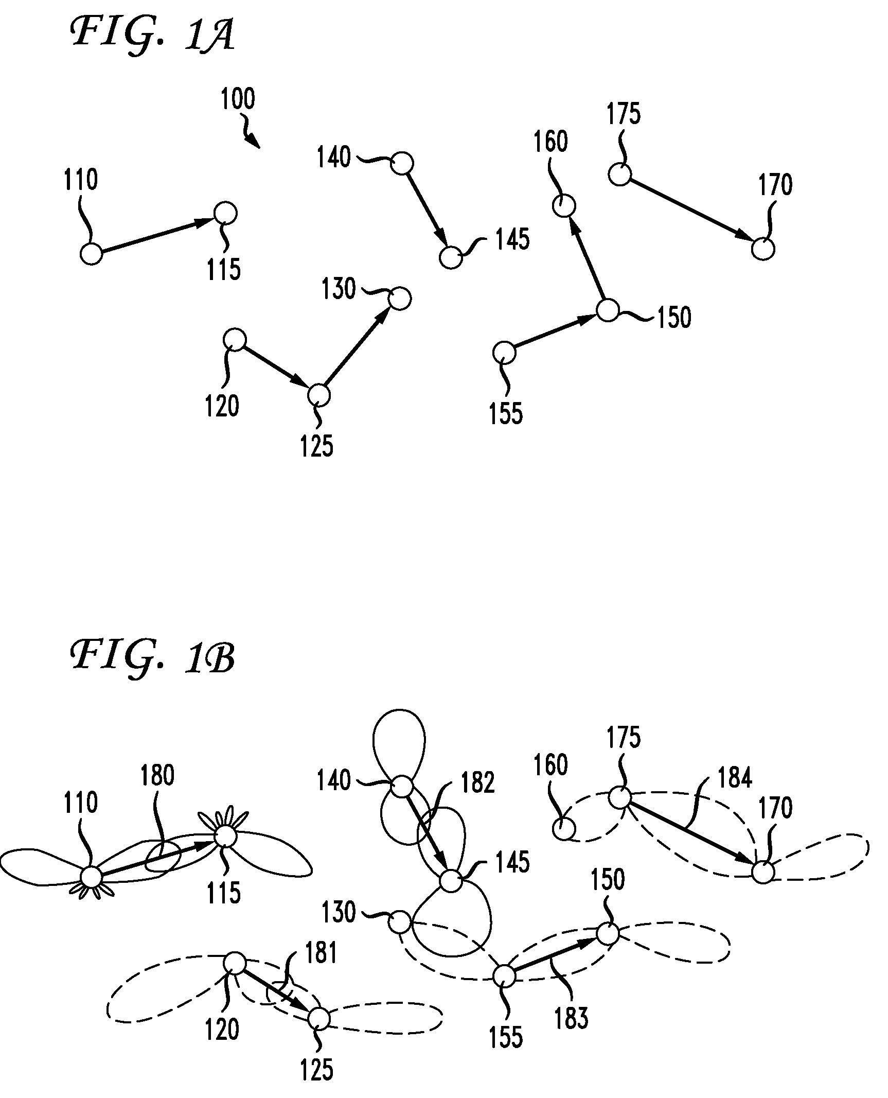
[0015]FIG. 1A is a diagram illustrating a wireless communication network 100 suitable for implementing one embodiment of the present invention. Wireless network 100 has, illustratively, a plurality of nodes 110-175, each having one or more wireless antennas, such as the antennas of Access Points (APs) at each node. Nodes 110-175 illustratively have an array of multiple cooperating antennas so as to take advantage of multiple input, multiple output (MIMO) techniques, as discussed above. Each node is, for example and without limitation, a node in a wireless backhaul multi-hop network.

[0016]In order to communicate with one another, the nodes 110-175 of FIG. 1A may use the multiple antennas in those nodes to perform adaptive beamforming. As will be familiar to one skilled in the art, adaptive beamforming is a technique in which an array of antennas is able to achieve maximum reception in a specific angular direction by estimating the signal arrival from a desired direction (in the prese...


PUM


Abstract

A method and apparatus is disclosed whereby the scheduling of network transmissions in a wireless backhaul network is determined using a cross-layer optimization algorithm. In a first embodiment, the algorithm assumes a good MAC layer transmit schedule has been provided and computes optimal network layer routes as well as transmit beam patterns and transmit powers in a semi-distributed manner. According to this embodiment, the optimization goal is the throughput from each access point, or node in the network, to the core network. In another embodiment, an independent set of transmitting nodes is determined at the MAC layer in a way such that no link in the set interferes with another link and no link is scheduled to transmit and receive at the same time. According to this embodiment, a column generation algorithm is used to find a maximal weighted independent set and to achieve optimal network transmission throughput.

Description

[0001]This application claims the benefit of U.S. Provisional Application No. 60 / 729,775, filed Oct. 24, 2005, which is hereby incorporated herein by reference.BACKGROUND OF THE INVENTION[0002]The present invention relates generally to medium access control in communication networks.[0003]Wireless data networks are used in many different applications as a cost-effective solution for transporting data from one point to another. Such networks are typically characterized by many individual users located at nodes distributed over a geographic area. Such networks typically use an access point (AP) based architecture in which APs aggregate wireless data from users within a certain geographic region and then transport this aggregated data traffic over a backhaul network from the APs to a core network, such as a service provider's network. In many cases, the service provider's network is the Internet. In some implementations, data from a user must make multiple wireless hops between access ...

Claims


Application Information

Patent Timeline
Patent Type & Authority Patents(United States)
IPC IPC(8): H04W4/00H04M1/00
CPCH04L47/14H04W40/06H04W52/343H04W40/00H04W84/18H04W52/346H04W52/42H04W52/46Y02D30/70H04W8/04
Inventor CAO, MINWANG, XIAODONGKIM, SEUNG-JUNMADIHIAN, MOHAMMAD
Owner NEC CORP
Learn More