
Method and system for communicating filter compensation coefficients for a digital power control system

a technology of filter compensation and digital power control system, applied in the direction of electric variable regulation, process and machine control, instruments, etc., can solve the problems of adding complexity and size to the overall electronic system

Inactive Publication Date: 2009-07-21
BEL POWER SOLUTIONS INC
View PDF237 Cites 23 Cited by
  • Summary
  • Abstract
  • Description
  • Claims
  • Application Information

AI Technical Summary

Problems solved by technology

A drawback with such a control system is that it adds complexity and size to the overall electronic system.

Method used


Image

  • Method and system for communicating filter compensation coefficients for a digital power control system
  • Method and system for communicating filter compensation coefficients for a digital power control system
  • Method and system for communicating filter compensation coefficients for a digital power control system

Examples


Embodiment Construction

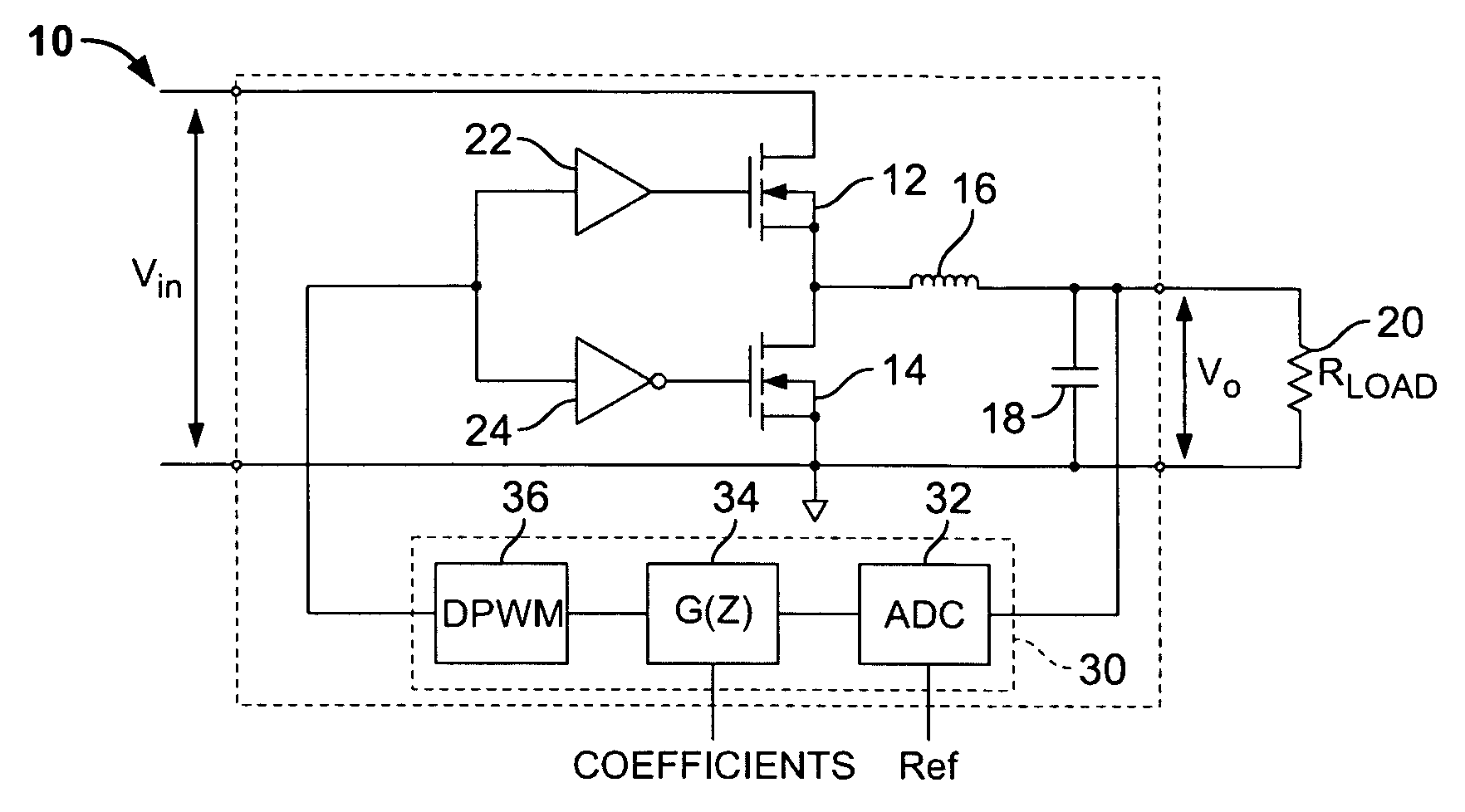
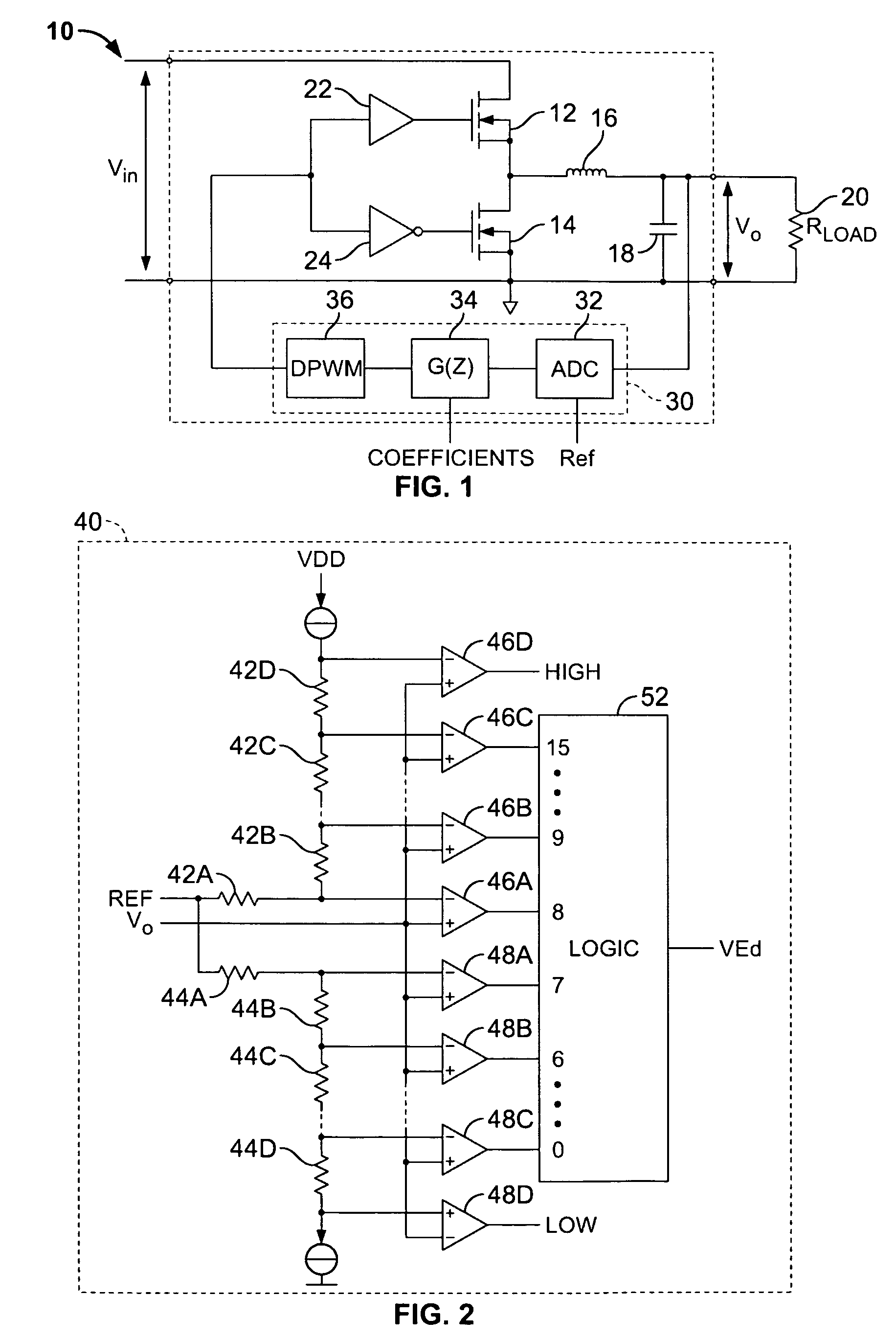
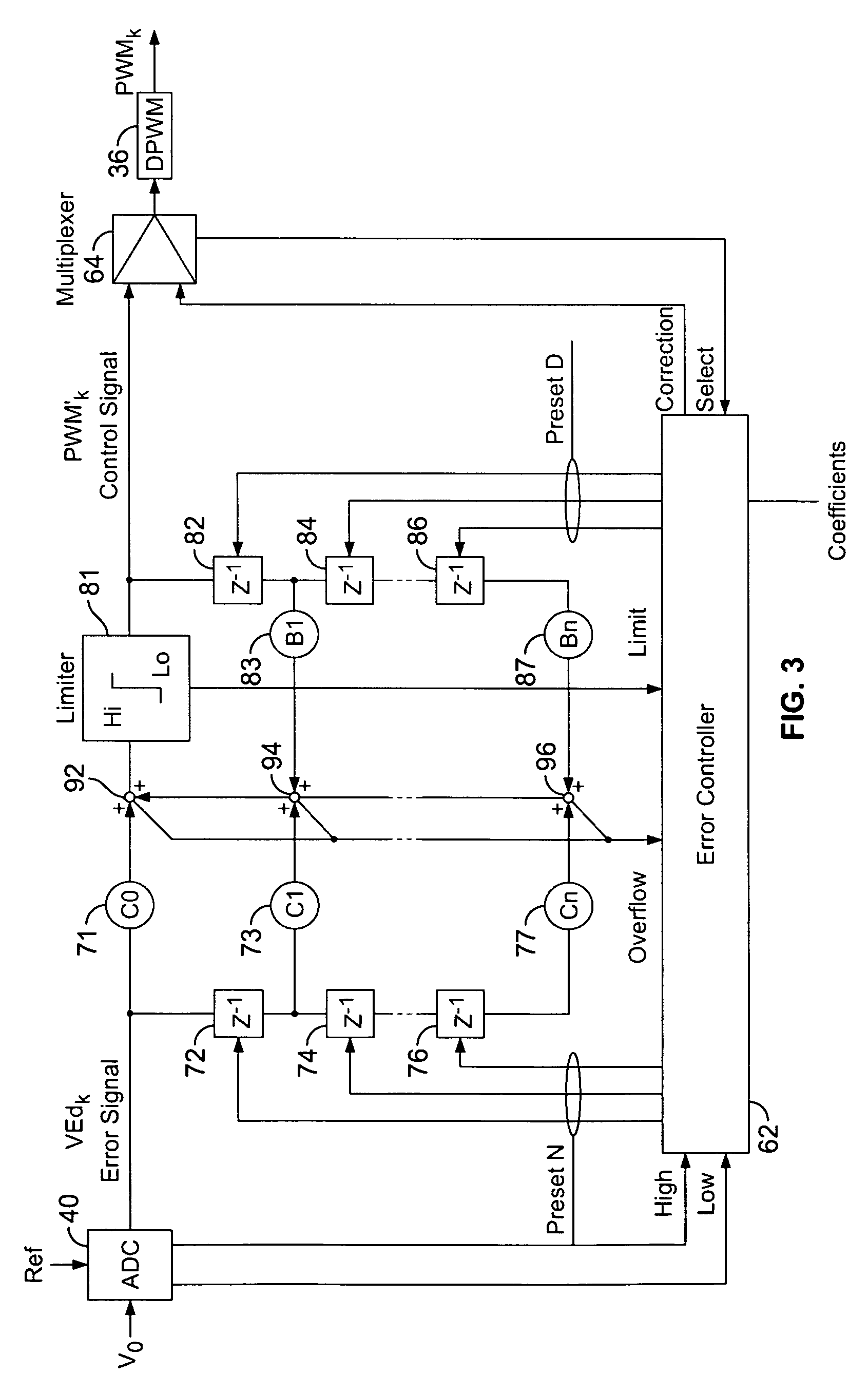
[0025]The present invention provides a method for digitally controlling a switched mode power supply. More particularly, the invention provides a a system and method for programming the digital filter compensation coefficients of a digitally controlled switched mode power supply within a distributed power system. In the detailed description that follows, like element numerals are used to describe like elements illustrated in one or more figures.

[0026]FIG. 1 depicts an exemplary switched mode power supply 10 having a digital control circuit in accordance with an embodiment of the present invention. The power supply 10 comprises a buck converter topology to convert an input DC voltage Vin to an output DC voltage Vo applied to a resistive load 20 (Rload). The power supply 10 includes a pair of power switches 12, 14 provided by MOSFET devices. The source terminal of the high side power switch 12 is coupled to the input voltage Vin, the source terminal of the low side power switch 14 is ...


PUM


Abstract

A method and system is provided for programming the digital filter compensation coefficients of a digitally controlled switched mode power supply within a distributed power system. The distributed power system comprises a plurality of point-of-load (POL) regulators each comprising at least one power switch adapted to convey power to a load and a digital controller adapted to control operation of the power switch responsive to a feedback measurement. The digital controller further comprises a digital filter having a transfer function defined by plural filter coefficients. A serial data bus operatively connects each of the plurality of POL regulators. A system controller is connected to the serial data bus and is adapted to communicate digital data to the plurality of POL regulators via the serial data bus. The digital data includes programming data for programming the plural filter coefficients. The system controller further comprises a user interface adapted to receive the programming data therefrom.

Description

RELATED APPLICATION DATA[0001]This patent application is a divisional application pursuant to 35 U.S.C. § 120 to U.S. patent application Ser. No. 10 / 889,806, filed Jul. 12, 2004, now issued as U.S. Pat. No. 7,249,267 on Jul. 24, 2007, which claims priority to provisional patent application Ser. No. 60 / 544,553, filed Feb. 12, 2004, and which also claims priority as a continuation-in-part pursuant to 35 § U.S.C. § 120 to patent applications Ser. No. 10 / 361,667, filed Feb. 10, 2003 now U.S. Pat. No. 6,933,709, and Ser. No. 10 / 326,222, filed Dec. 21, 2002 now U.S. Pat. No. 7,000,125.BACKGROUND OF THE INVENTION[0002]1. Field of the Invention[0003]The present invention relates to power supply circuits, and more particularly to digital power control systems and methods for programming parameters of switched mode power supply circuits.[0004]2. Description of Related Art[0005]Switched mode power supplies are known in the art to convert an available direct current (DC) or alternating current ...

Claims


Application Information

Patent Timeline
Patent Type & Authority Patents(United States)
IPC IPC(8): G06F1/26H02J1/08H02J1/10H02J13/00H02M3/157H02M3/335
CPCH02J1/08H02J13/0003H02M3/157H02M3/33515H02J1/102H02M2001/008H02M2001/0012H02J2001/008H02J1/082H02M1/0012H02M1/008H02J13/00016H02J13/00036H02J13/00
Inventor CHAPUIS, ALAIN
Owner BEL POWER SOLUTIONS INC
Learn More