
Shift control device and shift control method of automatic transmission

a technology of automatic transmission and control device, which is applied in the direction of mechanical equipment, transportation and packaging, roads, etc., can solve the problems of increasing speed, increasing burden on friction engagement devices, and affecting so as to secure the durability of friction engagement devices. , the effect of ensuring the durability of friction engagement devices

Inactive Publication Date: 2009-07-21
TOYOTA JIDOSHA KK
View PDF10 Cites 14 Cited by
  • Summary
  • Abstract
  • Description
  • Claims
  • Application Information

AI Technical Summary

Benefits of technology

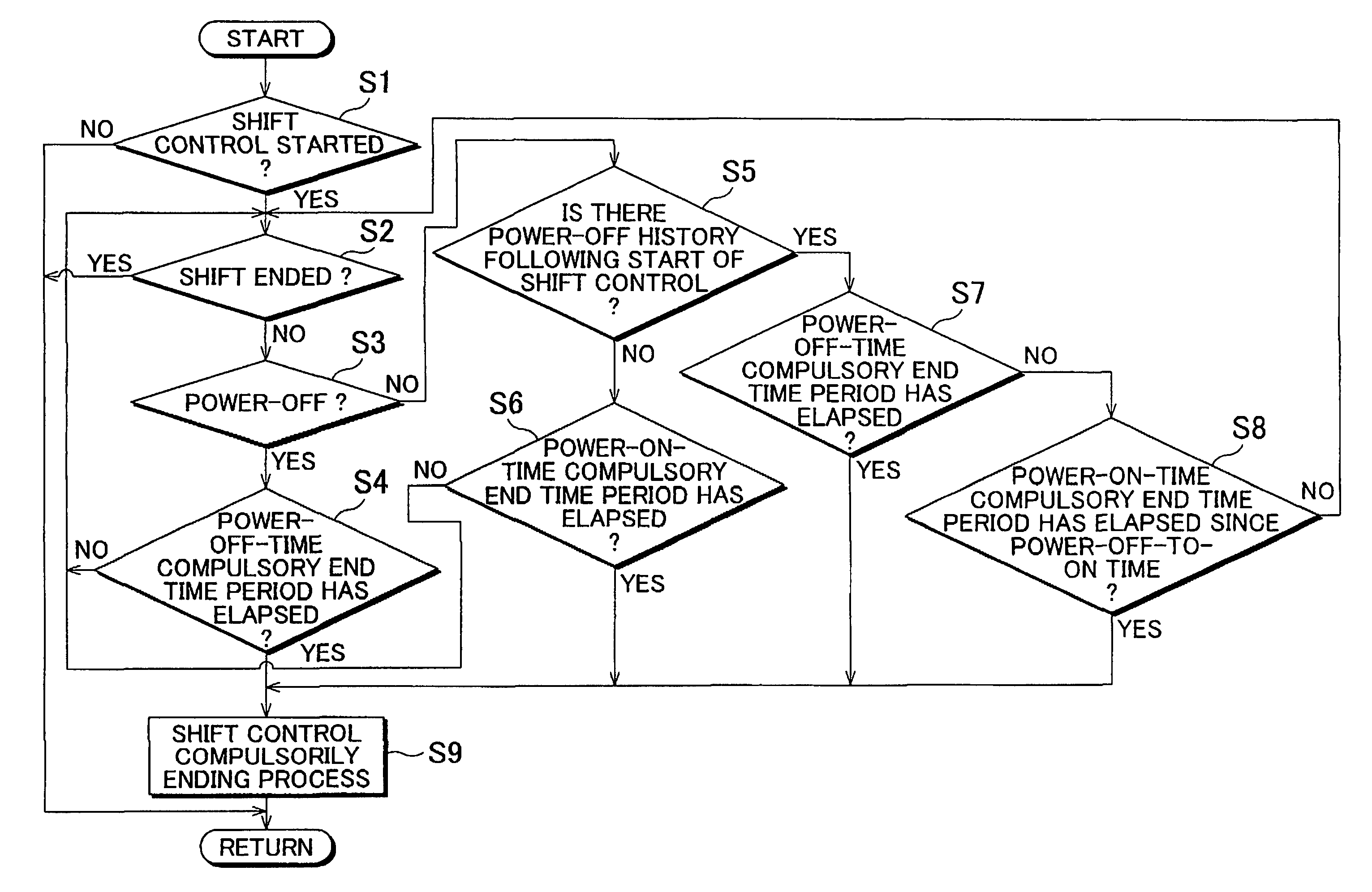
This approach ensures appropriate and shock-free transition of shifting actions, securing the durability of friction engagement devices by setting tailored time thresholds for each shift state and preventing immediate compulsory ending during power-on transitions from power-off shifts.

Problems solved by technology

For example, in an upshift during a power-on state where the accelerator is turned on, the input shaft rotation speed that is apt to rise needs to be compulsorily declined by engaging a corresponding friction engagement device, and therefore the burden exerted on the friction engagement device is large.
In such an upshift, since a corresponding friction engagement device is engaged after the input shaft rotation speed has naturally declined due to engine friction and the like, the shifting action takes a relatively long time and, besides, the burden on the friction engagement device is small.
However, in the case where a power-off shift is switched to a power-on shift due to the turning-on of the accelerator halfway through the power-off shift, the corresponding switching of the aforementioned predetermined time period may sometimes result in a shift shock or the like.

Method used


Image

  • Shift control device and shift control method of automatic transmission
  • Shift control device and shift control method of automatic transmission
  • Shift control device and shift control method of automatic transmission

Examples


Embodiment Construction

[0039]In the following description and the accompanying drawings, the present invention will be described in more detail with reference to exemplary embodiments.

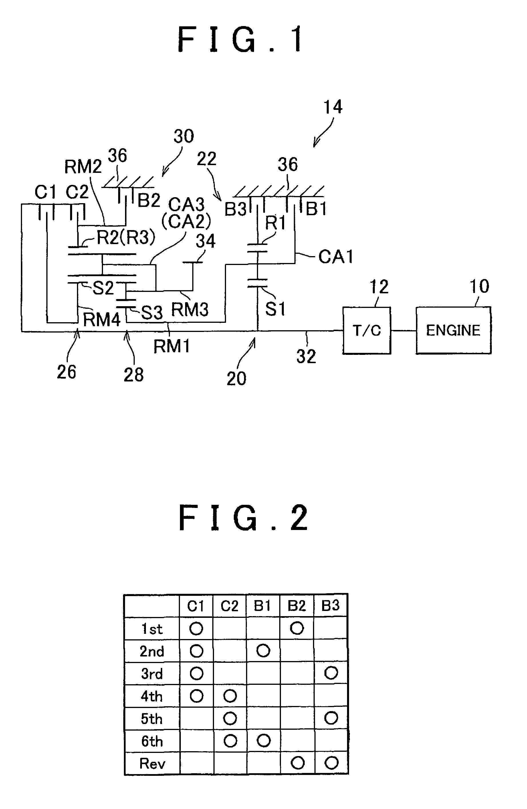
[0040]FIG. 1 is a skeleton diagram of a transversely mounted type vehicular drive apparatus, such as an FF (front engine, front wheel drive) vehicle or the like, in which the output of an engine 10 constructed of an internal combustion engine, such as a gasoline engine or the like, is transferred to driving wheels (front wheels) via a torque converter 12, an automatic transmission 14, and a differential gear device (not shown). The engine 10 is a power source for running the vehicle, and the torque converter 12 is a coupling that employs a fluid.

[0041]The automatic transmission 14 has, on the same axis, a first speed change portion 22 constructed mainly of a single pinion-type first planetary gear device 20, and a second speed change portion 30 constructed mainly of a single pinion-type second planetary gear device 26 and a ...


PUM


Abstract

In a shift control device and a shift control method of an automatic transmission that establishes a plurality of gear steps of different speed change ratios by selectively engaging a plurality of friction engagement devices, one of a shift start time point and an inertia phase start time point is used as a reference time. In a power-off shift, the shift action is compulsorily ended when the elapsed time from the reference time exceeds a first time. In a power-on shift, the shift action is compulsorily ended when the elapsed time from the reference time exceeds a second time that is set shorter than the first time. If a switch from the power-off shift to the power-on shift occurs halfway through the power-off shift, the shift action is compulsorily ended when the elapsed time from the time point of the switch exceeds a predetermined time.

Description

INCORPORATION BY REFERENCE[0001]The disclosure of Japanese Patent Applications No. 2005-312037 filed on Oct. 26, 2005, including the specification, drawings and abstract is incorporated herein by reference in its entirety.BACKGROUND OF THE INVENTION[0002]1. Field of the Invention[0003]The invention relates to a shift control device and a shift control method of an automatic transmission. In particular, the invention relates to a compulsory end timing period for compulsorily ending the shifting action through an oil pressure control or the like if the shift does not end.[0004]2. Description of the Related Art[0005]In a shift control device of an automatic transmission that establishes a plurality of gear steps of different speed change ratios by selectively engaging a plurality of friction engagement devices, it has been proposed that a shift start time point or an inertia start time point is defined as a reference time point, and that if a shift does not end although the elapsed tim...

Claims


Application Information

Patent Timeline
Patent Type & Authority Patents(United States)
IPC IPC(8): F16H61/12F16H59/18F16H59/68F16H61/02F16H61/68F16H61/684F16H61/686
CPCF16H61/08F16H61/686F16H2200/0052F16H2200/2007Y10T477/693F16H2061/0492Y10S477/906Y10T477/65Y10T477/6937F16H2061/0496Y02T10/60
Inventor AYABE, ATSUSHISUGIMURA, TOSHIOTSUTSUMI, TAKAHIKOISHIHARA, HISASHIIKETOMI, KAZUHIROTAKAIE, YOSUKE
Owner TOYOTA JIDOSHA KK
Learn More