
Optical pickup

a pickup and optical technology, applied in the field of optical disc devices, can solve the problems of increasing power consumption, equipping the optical pickup with objective lenses, and increasing the thickness of the optical pickup, and achieve the effect of convenient compactness and thinness

Active Publication Date: 2009-07-14
FUJITSU LTD
View PDF12 Cites 2 Cited by
  • Summary
  • Abstract
  • Description
  • Claims
  • Application Information

AI Technical Summary

Benefits of technology

The present invention provides an optical pickup that can be made compact and thin without compromising its functions. The pickup includes a movable member, objective lenses, coil blocks, magnets, and a reflector. The center portion of the movable member is thinner than its sides, allowing the reflector to be positioned close to the center portion. The pickup is designed to be easily incorporated into optical disc devices. The technical effects of the invention include reduced thickness of the optical pickup and improved performance.

Problems solved by technology

In order to enable recording onto and reproduction from a plurality of types of optical discs having different optical characteristics using a single optical pickup, a major issue is how to equip the optical pickup with objective lenses.
When the objective lens along accounts for this 4.5 mm thickness, considering that the standing mirror is placed directly below the objective lens, there has been the problem that the thickness of the optical pickup becomes larger than the thickness of slim drives (7.3 mm) used in notebook computers, which serve as one yardstick of thinness.
However, there are the problems that, when magnetic circuits are made compact the driving performance in the focusing direction or the radial direction declines, power consumption increases, and the tracking precision declines, so that there are difficulties attending a compact design for magnetic circuits.
Further, the size of the standing mirror depends on the effective diameter of the objective lenses; as optical design conditions, the width of the laser light beam reflected by the standing mirror must be larger than the effective diameter of the objective lens, so that reduction of the size of the standing mirror and a thin design are extremely difficult to achieve.

Method used


Image

  • Optical pickup
  • Optical pickup
  • Optical pickup

Examples


Embodiment Construction

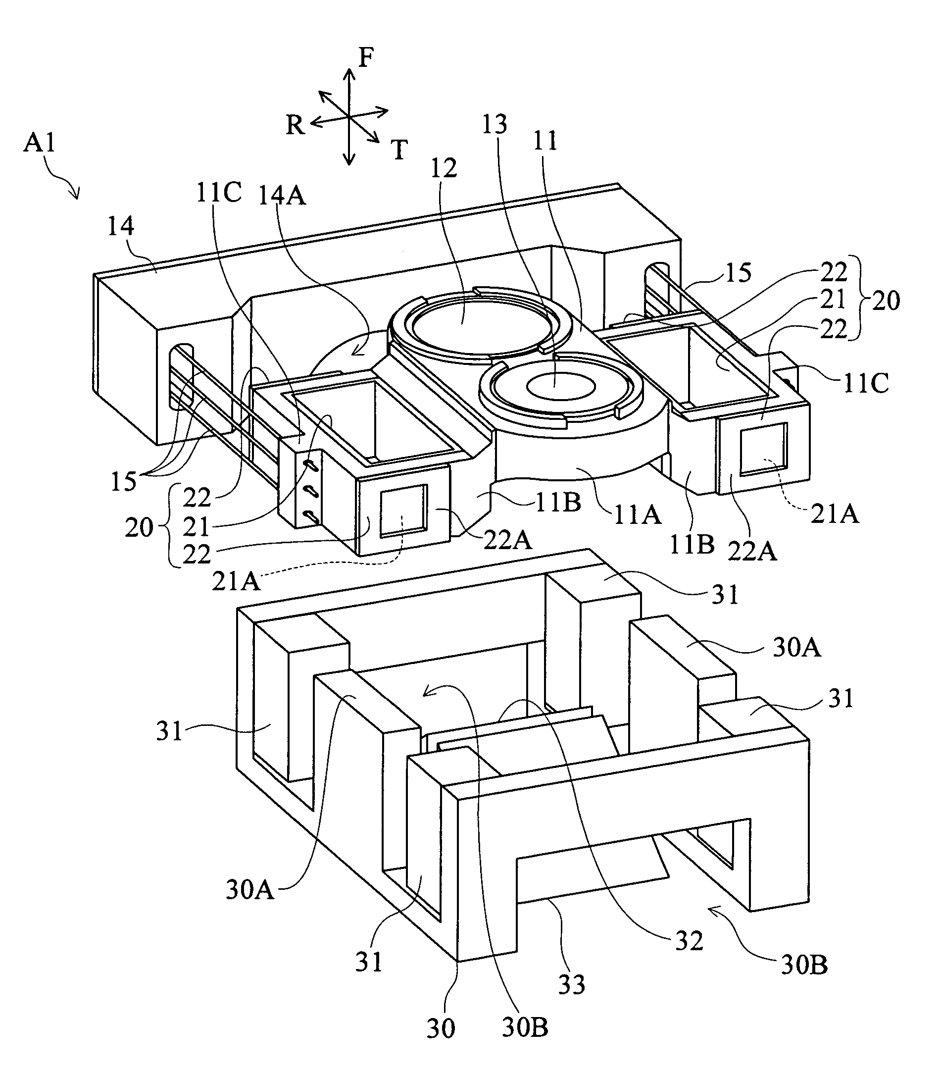
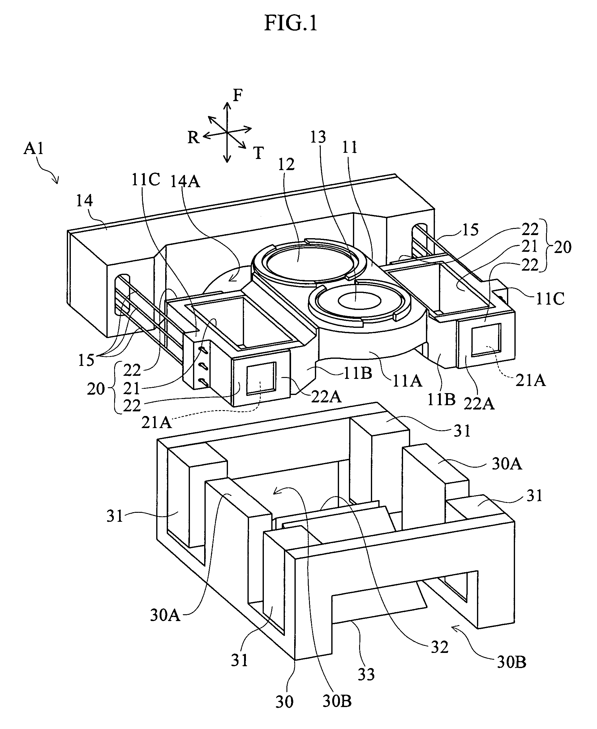
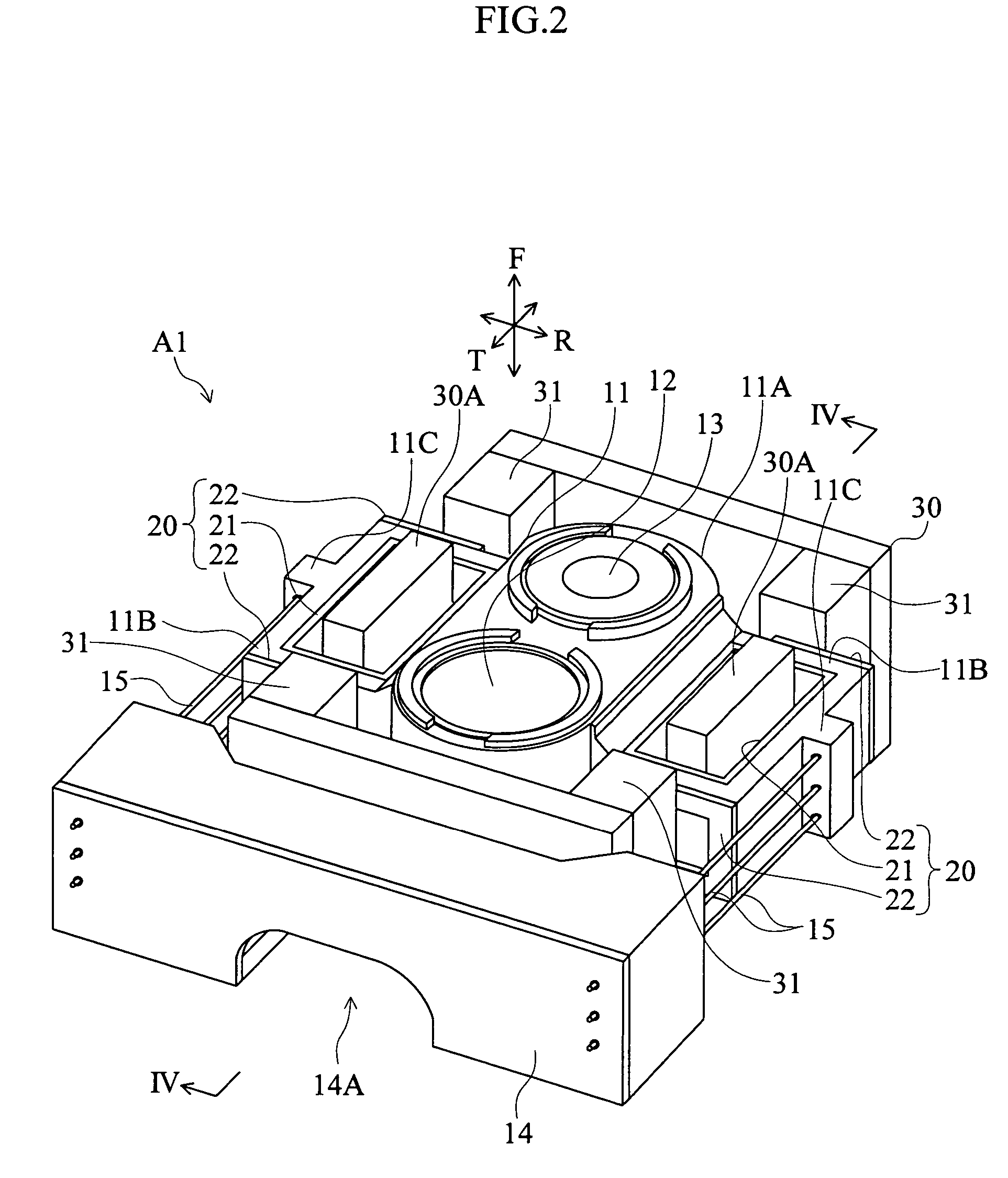
[0044]FIG. 1 through FIG. 5 show a first aspect of an optical pickup of the invention. The optical pickup A1 of this aspect is equipped with two types of lens, corresponding to a plurality of optical discs (for example, Blu-ray discs, DVDs, and CDs) with different optical characteristics, and are used for optical recording onto and reproduction from the optical discs. In each of the diagrams, the side on which optical discs are positioned in the optical pickup A1 is considered as the upper side, the vertical direction is the focusing direction F, the direction along the radius of the optical disc is the radial direction R, and the third direction along the circumference of the optical disc, which is perpendicular to both the focusing direction F and the radial direction R, is the tangential direction T.

[0045]As shown in FIG. 1 and FIG. 2, the optical pickup A1 has a movable member 11; two objective lenses 12 and 13; a holder 14; a plurality of support wires 15; two coil blocks 20, f...


PUM

PropertyMeasurementUnit
thickness Taaaaaaaaaaa
thickness Tbaaaaaaaaaa
thicknessaaaaaaaaaa

Abstract

An optical pickup is provided for driving objective lenses in focusing and radial directions. The pickup includes a movable member, and objective lenses at the center portion of the movable member. The pickup also includes coil blocks provided at two side portions of the movable member, and pairs of magnets flanking the coil blocks in a tangential direction perpendicular to the focusing and radial directions. Support members are attached to the side portions of the movable member, permitting the movable member to move in the focusing direction and the radial direction. Each coil block includes focusing and tracking coils for driving the movable member in the focusing direction and the radial direction. The center portion of the movable member, below which a reflector is arranged, is thinner than the side portions of the movable member.

Description

BACKGROUND OF THE INVENTION[0001]1. Field of the Invention[0002]This invention relates to an optical disc device to perform recording onto and reproduction from an optical disc, and in particular relates to an optical pickup in an optical disc device. More specifically, this invention relates to an optical pickup equipped with a plurality of objective lenses, so as to enable recording onto and reproduction from a plurality of types of optical discs having different optical characteristics.[0003]2. Description of the Related Art[0004]Various configurations have been devised for optical pickups for optical disc devices to enable recording and reproduction using a plurality of types of optical discs having different optical characteristics. In particular, due to the appearance of Blu-ray discs, which are high-density recording media, hereafter optical disc devices will be sought which are capable of recording onto and reproduction from blue-light optical discs (HD-DVD and Blue-ray disc...

Claims


Application Information

Patent Timeline
Patent Type & Authority Patents(United States)
IPC IPC(8): G11B7/085
CPCG11B7/0933G11B7/0935G11B7/1374G11B7/0956G11B2007/0006
Inventor SHIMOKAWA, SATOSHITEZUKA, KOUICHI
Owner FUJITSU LTD
Learn More