Multicarrier receiver and transmitter with delay correcting function
a receiver and delay correction technology, applied in multi-frequency code systems, phase-modulated carrier systems, baseband system details, etc., can solve problems such as difficulty in analysing power amplifier distortion, and achieve the effect of not increasing the configuration of each analog section in cost and siz
- Summary
- Abstract
- Description
- Claims
- Application Information
AI Technical Summary
Benefits of technology
Problems solved by technology
Method used
Image
Examples
first preferred embodiment
[0057]FIG. 1 is a configuration diagram showing an essential part of a first embodiment of a multicarrier receiver according to the present invention and shows only constituent portions different from FIG. 15 and their peripheries. Reference numeral 201 indicates an F-LPF (Fractional Low Pass Filter). Constituent portions corresponding to those shown in FIG. 15 are given the same reference numerals respectively, and dual explanations thereof are omitted.
[0058]In the same drawing, the first embodiment includes the F-LPF 201 provided in a stage subsequent to an LPF 108 under the configuration shown in FIG. 15. Incidentally, it is also possible to combine the LPF 108 and the F-LPF 201 together and allow the LPF 108 to share the role of the F-LPF 201. However, these functions are illustrated in parts to make easy understanding. Any HPF, LPF and BPF may be adopted as the F-LPF 201 if their functions are satisfied.
second preferred embodiment
[0059]FIG. 2 is a configuration diagram showing an essential part of a second embodiment of a multicarrier receiver according to the present invention and illustrates only constituent portions different from FIG. 15 and their peripheries. Reference numeral 202 indicates an F-BPF (Fractional Band Pass Filter). Constituent portions corresponding to those shown in FIG. 15 are given the same reference numerals respectively, and dual explanations thereof are omitted.
[0060]In the same drawing, the second embodiment includes the F-BPF 202 provided between an A / D converter 106 and a quadrature detector 107 under the configuration shown in FIG. 15. Incidentally, any of HPF, LPF and BPF may be used as the F-BPF 202 if their functions are satisfied.
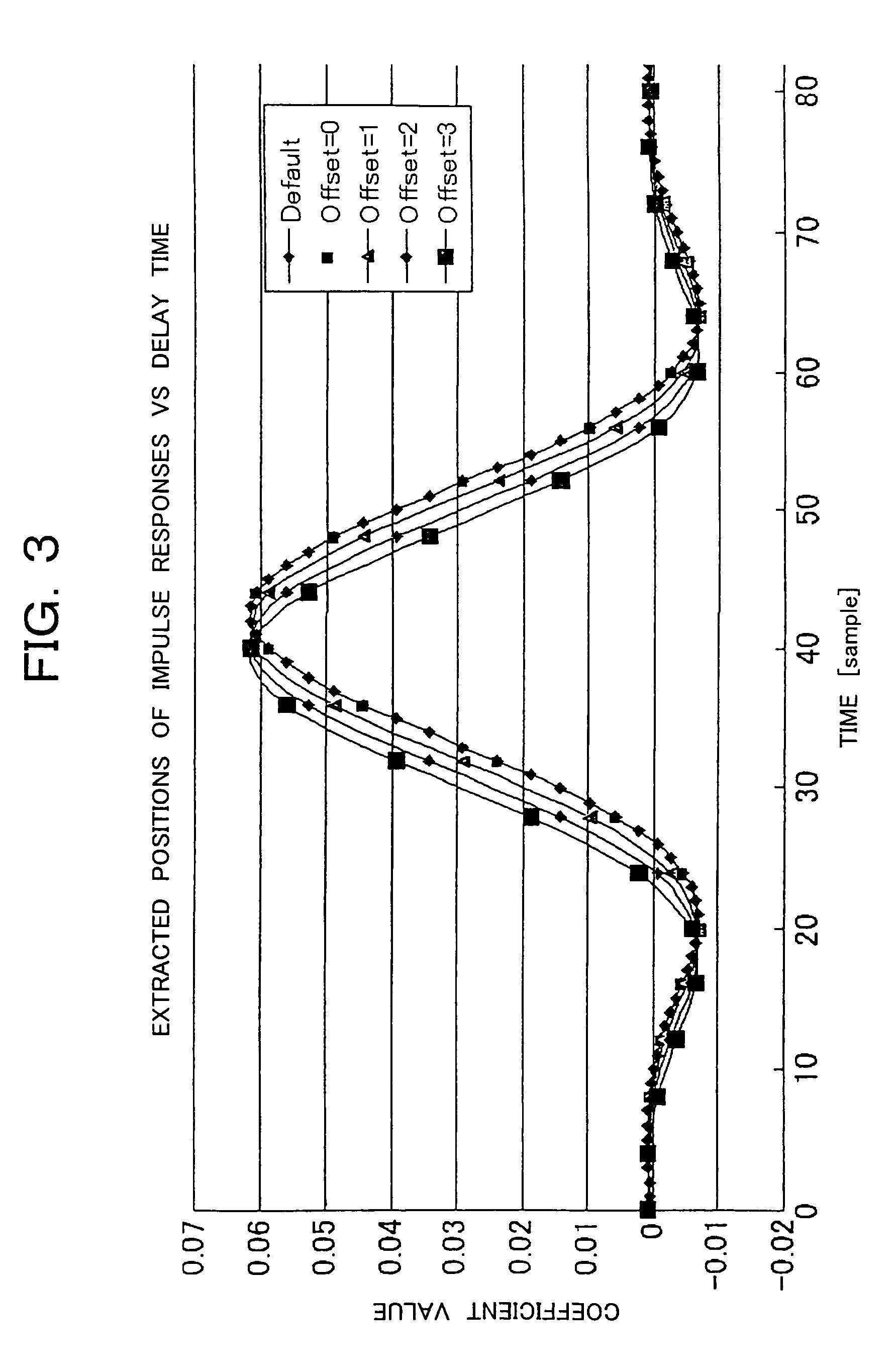
[0061]The principle of delay correction by filters will be explained below using FIG. 3.
[0062]FIG. 3 shows impulse responses designed for a given LPF, which are extracted every 4 samples from positions where they are shifted by 0 to 4 samples. That ...
third preferred embodiment
[0064]FIG. 4 is a configuration diagram showing an essential part of a third embodiment of a multicarrier receiver according to the present invention, which is suitable for use in an RRU (Remote Radio Unit, which is also called forward base station or extension base station) in a CDMA cellular phone infrastructure. Reference numerals 401 and 402 are shift registers respectively. Constituent portions corresponding to those shown in FIGS. 15 and 1 are given the same reference numerals respectively.
[0065]In the same drawing, the third embodiment includes the shift register 401 provided between the A / D converter 106 and the quadrature detector 107, and the shift register 402 provided between the LPF 108 and F-LPF 201 for I and Q phases under the configurations shown in FIGS. 15 and 1. Incidentally, a section prior to the A / D converter 106 is identical to the configuration shown in FIG. 15. Thus, the third embodiment is different from the first embodiment in that the shift registers 401 ...
PUM
 Abstract
Description
Claims
Application Information
 - R&D
- Intellectual Property
- Life Sciences
- Materials
- Tech Scout
- Unparalleled Data Quality
- Higher Quality Content
- 60% Fewer Hallucinations
Browse by: Latest US Patents, China's latest patents, Technical Efficacy Thesaurus, Application Domain, Technology Topic, Popular Technical Reports.
© 2025 PatSnap. All rights reserved.Legal|Privacy policy|Modern Slavery Act Transparency Statement|Sitemap|About US| Contact US: help@patsnap.com


