
Multi-function robotic device

a robotic device and multi-functional technology, applied in the field of robotic devices, can solve the problems of inefficiency, laborious, messy, and difficulty in distributing multiple consumables for use with a single device, and conventional technology has failed to provide a simple and efficient way for the owner or operator of the robotic devi

Active Publication Date: 2009-06-30
VORWERK & CO INTERHOLDING GMBH
View PDF20 Cites 192 Cited by
  • Summary
  • Abstract
  • Description
  • Claims
  • Application Information

AI Technical Summary

Benefits of technology

The present invention provides a multi-function robotic device that can perform various functions based on the characteristics of a functional cartridge. The device includes a body with a drive mechanism and an electronics module to provide instructions to the drive mechanism. The device also has a sensing apparatus to provide data related to the position of the robot relative to an object or an obstacle in the operating environment. The device can selectively attach a functional cartridge to the body to perform different functions. The technical effects of the invention include improved versatility, efficiency, and flexibility of the robotic device.

Problems solved by technology

From a consumer's perspective, it is generally recognized that the handling and installation of such consumables can be difficult, laborious, messy, or a combination of each.
From a manufacturer's perspective, distribution of multiple consumables for use with a single device can be inefficient, difficult (e.g., due to distribution channel constraints), or both.
Conventional technology has failed to provide a simple and efficient way for an owner or operator of a robotic device to replenish consumables required by the device.
In that regard, primitive navigation systems cause conventional devices to ricochet around an operating environment inefficiently; these devices reactively carom off of obstacles and repeatedly re-visit areas that have already been treated, wasting valuable consumables and battery capacity.
For example, a robotic device tasked with cleaning a kitchen floor may present a hazard to occupants of the kitchen if it remains in a traffic area even after it has completed a cleaning cycle.
Conventional mechanisms (such as “docking” or charging stations) that purport to facilitate robot storage are deficient; as a result of inefficient mechanical and electrical mating structures, as well as inadequate navigational capabilities, many robots cannot reliably and consistently engage with conventional docking or charging stations.
While failing to provide a reliable robot storage and charging solution, conventional implementations also generally fail to allow a robot to view its operating environment from an advantageous perspective when engaged in its base or charging station.
Such a floor mopping robot cannot be reconfigured to perform other operations (e.g., vacuuming a floor or waxing a floor) without significant structural modifications; in addition, sensor reconfiguration, software reprogramming, or some combination thereof is also required in order to alter the overall functionality of a typical robotic platform.
Conventional technology has failed to provide a simple and efficient way for an owner or operator of a robotic device selectively to reconfigure the device to perform a desired function.

Method used


Image

  • Multi-function robotic device
  • Multi-function robotic device
  • Multi-function robotic device

Examples


Embodiment Construction

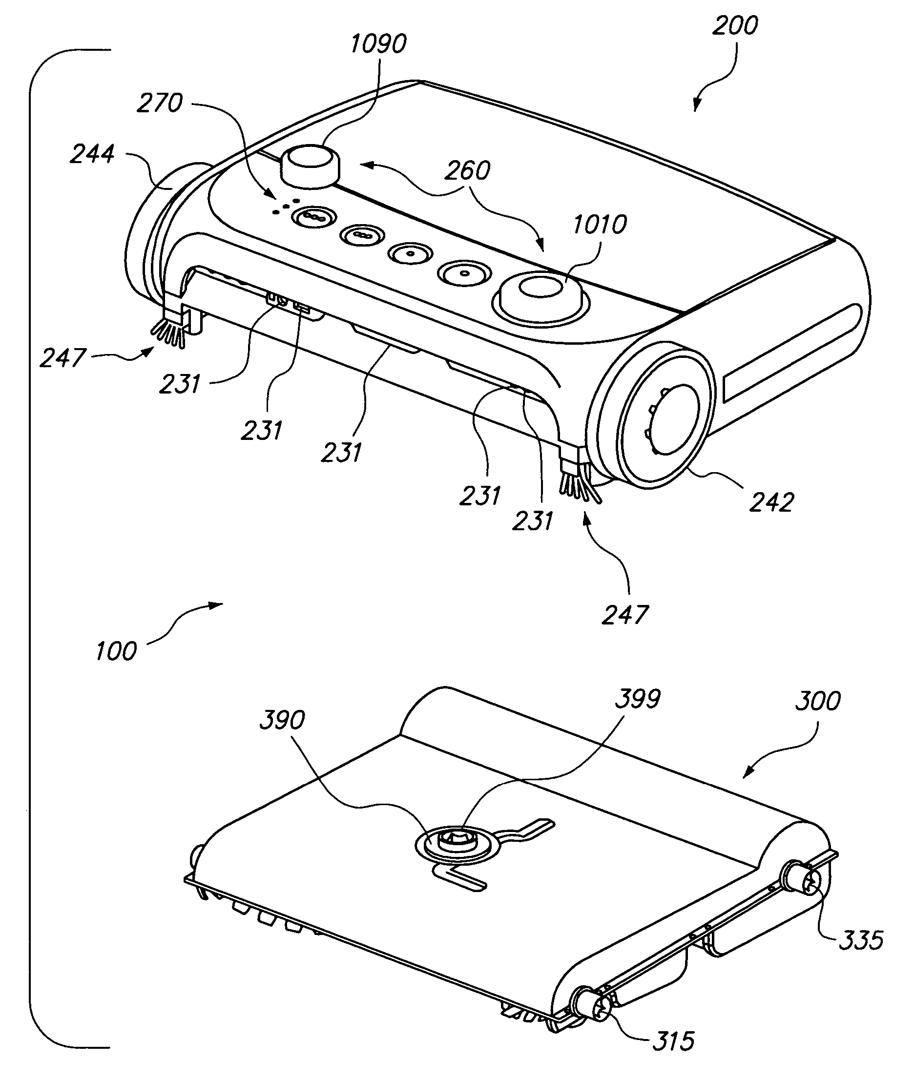
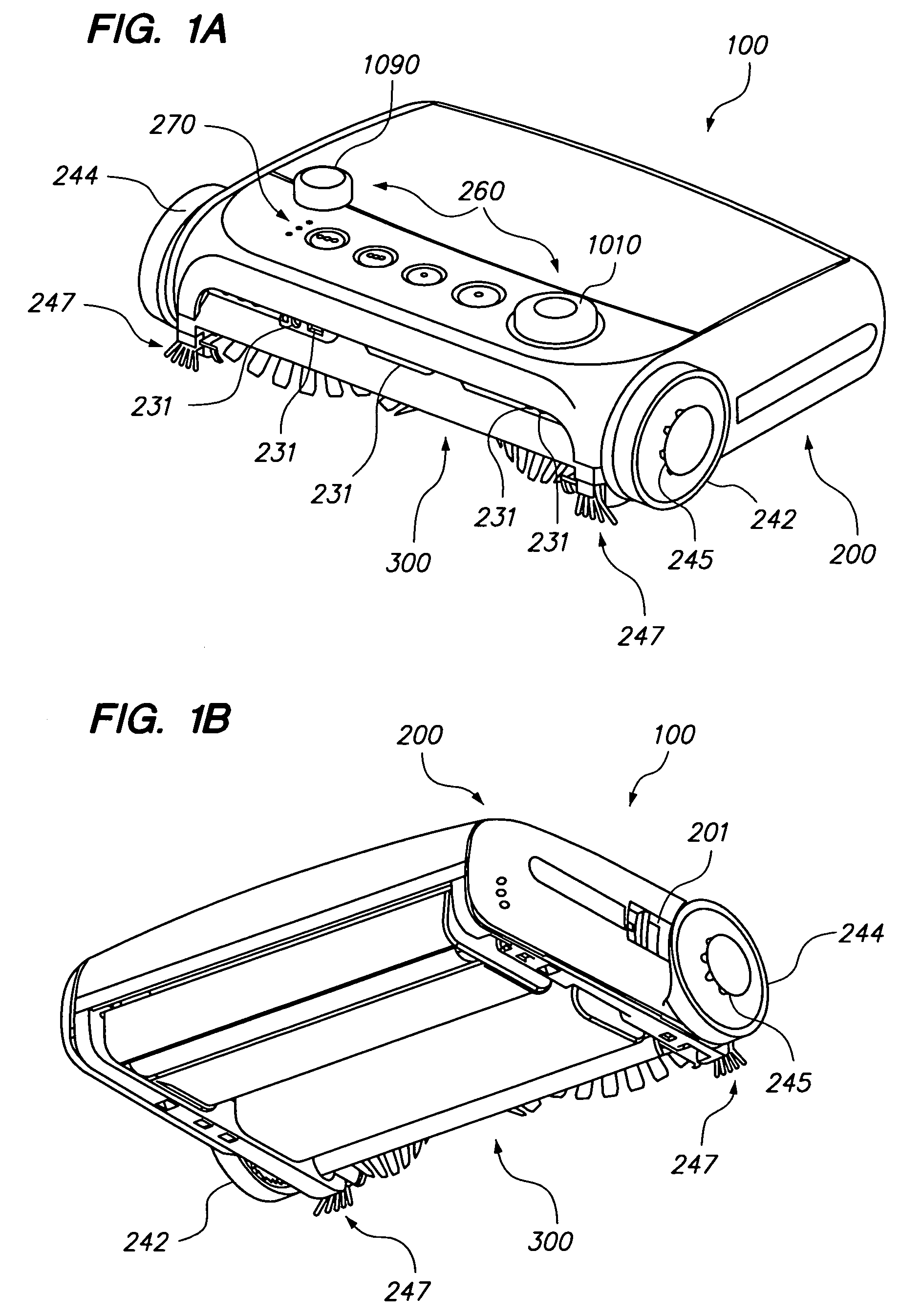
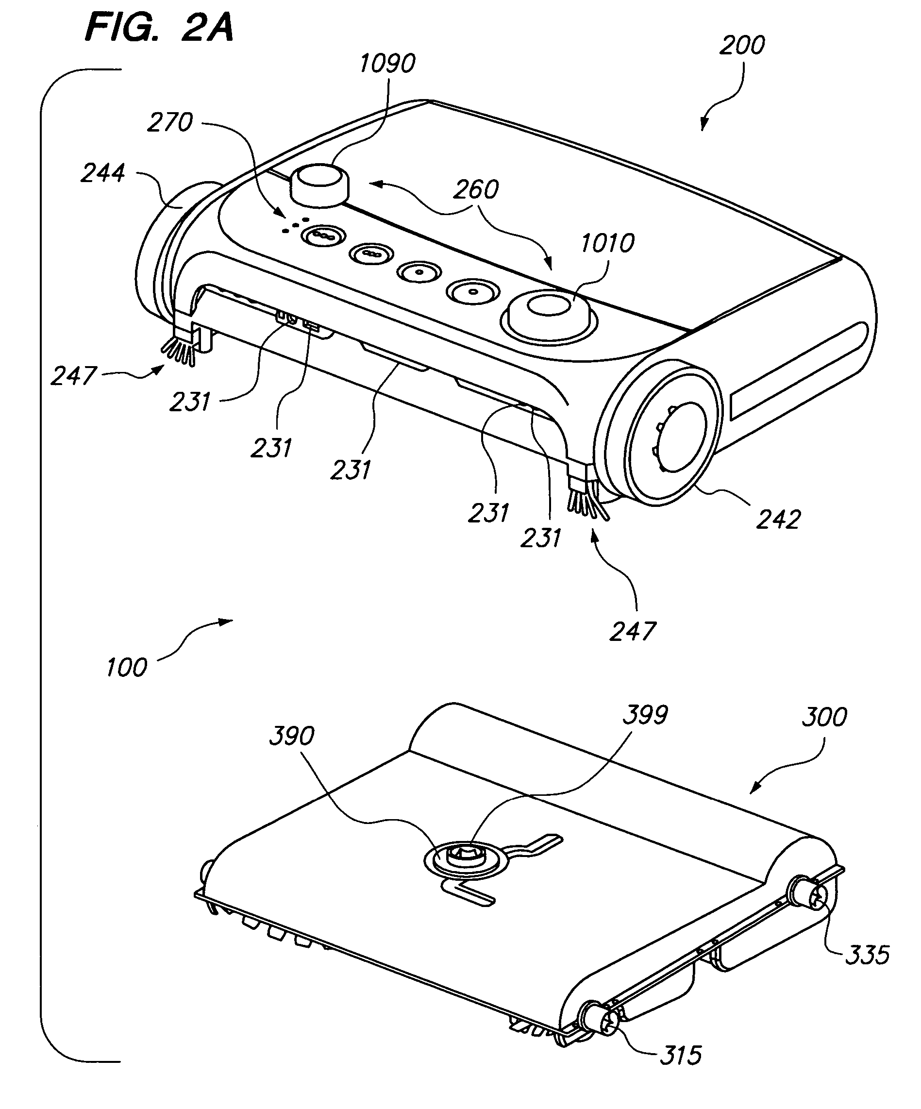
[0048]With reference now to the drawing figures, FIGS. 1A and 1B are bird's eye and worm's eye perspective views, and FIGS. 2A and 2B are bird's eye and worm's eye partially exploded perspective views, of an exemplary embodiment of a multi-function robotic device.

[0049]It will be appreciated that a multi-function robotic device (“robot”) 100 may generally be characterized by an ability to perform tasks autonomously or automatically with little or no intervention on the part of a user or operator.

[0050]In that regard, robot 100 may generally comprise computer hardware and software operative to provide some degree of intelligence and otherwise to control or influence operation of the various electromechanical and other structural elements described below. The overall shape, physical dimensions, structural orientation or arrangement, and operational characteristics of the various components are all susceptible of numerous modifications that will be readily appreciated by those of skill...


PUM


Abstract

A multi-function robotic device may have utility in various applications. In accordance with one aspect, a multi-function robotic device may be selectively configurable to perform a desired function in accordance with the capabilities of a selectively removable functional cartridge operably coupled with a robot body. Localization and mapping techniques may employ partial maps associated with portions of an operating environment, data compression, or both.

Description

CROSS-REFERENCE TO RELATED APPLICATIONS[0001]The present application claims the benefit of the following co-pending U.S. provisional application Ser. No. 60 / 713,838, filed Sep. 2, 2005, entitled “CARTRIDGE FOR ROBOTIC DEVICES”; Ser. No. 60 / 722,781, filed Sep. 29, 2005, entitled “LASER AND CAMERA-BASED FEATURES FOR CONSUMER ROBOTS”; and Ser. No. 60 / 722,856, filed Sep. 29, 2005, entitled “WALL BASE AND SELF-RECHARGING FEATURES FOR SELF-MOBILE ROBOTS”. The disclosures of the foregoing provisional applications are hereby incorporated herein by reference in their entireties.BACKGROUND[0002]1. Field of the Invention[0003]Aspects of the present invention relate generally to the field of robotic devices, and more particularly to a multi-function robotic device having utility in various applications.[0004]2. Description of Related Art[0005]Automatic or autonomous devices (i.e., robotic devices or robots) that can be used for home and commercial applications, such as cleaning, often utilize c...

Claims


Application Information

Patent Timeline
Patent Type & Authority Patents(United States)
IPC IPC(8): B08B7/04G05B19/18G05B19/042
CPCA47L5/225B25J9/0003B25J9/1664B25J9/1679G05D1/0225G05D1/0231G05D1/0274A47L9/009A47L2201/04A47L2201/00G05B2219/36513G05B2219/40095G05B2219/40423G05B2219/40506G05D2201/0215G05D1/024A47L9/28B25J5/00G06F9/00G05B15/00
Inventor AUGENBRAUN, JOEHIRSCHHORN, LINDASHAH, PANKAJDONALDSON, NICKJAYNE, WILLIAMGOMEZ, JUAN B.PINZARRONE, JOSEPH
Owner VORWERK & CO INTERHOLDING GMBH
Learn More