Intake control device for vehicle engine
a technology of vehicle engine and control device, which is applied in the direction of electric control, machine/engine, combustion air/fuel air treatment, etc., can solve the problems of unsuitable isc technique, complicated device structure, and increased device cost, and achieve the effect of simple structur
- Summary
- Abstract
- Description
- Claims
- Application Information
AI Technical Summary
Benefits of technology
Problems solved by technology
Method used
Image
Examples
first embodiment
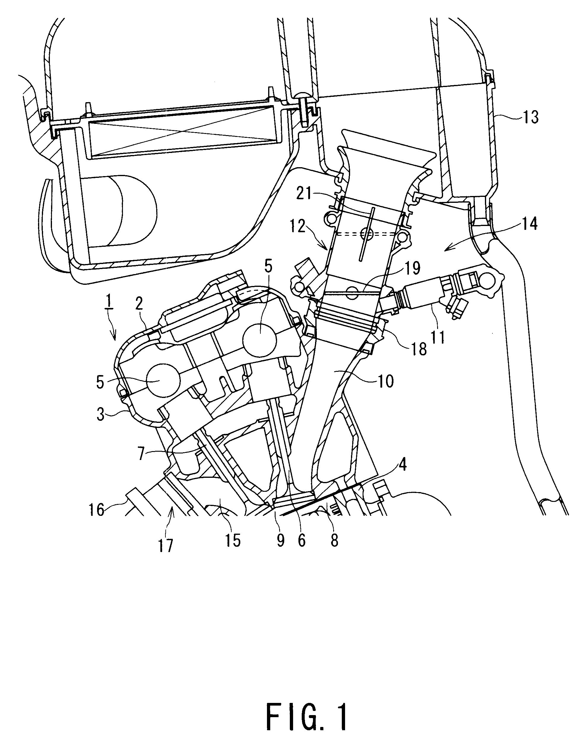
[0064]With reference to FIG. 1 showing a partial longitudinal sectional view of a motorcycle engine and intake system according to the present invention, an engine 1 mainly includes a cylinder head cover 2, a cylinder head 3, a cylinder block 4, and a crank case, not shown, to thereby form an outer configuration thereof.
[0065]A pair of front and rear cam shafts 5, 5 constituting a valve gear (valve moving unit) is provided in the cylinder head 3. The cam shafts 5, 5 serve to open or close intake / exhaust valves 6, 7 in the cylinder head 3. An upper opening of the cylinder head 3 is closed with the cylinder head cover 2.
[0066]On the other hand, a piston 8 is slidably inserted into the cylinder block 4. A combustion chamber 9 is formed between the cylinder head 3 and the piston 8, and an ignition plug, not shown, is externally screwed to the center thereof.
[0067]An air fuel mixture is supplied to the engine 1 by a fuel injection system. A throttle body 12 provided with a fuel injector ...
third embodiment
[0085]In FIG. 10A, the sub-throttle valve 21 is fully closed. In FIG. 10B, the sub-throttle valve 21 is half-opened. In FIG. 10C, the sub-throttle valve 21 is fully opened. As shown in FIGS. 10A to 10C, in the third embodiment, the ISC valve 32b is a wedge-shaped groove-like cutout as seen in a side view.
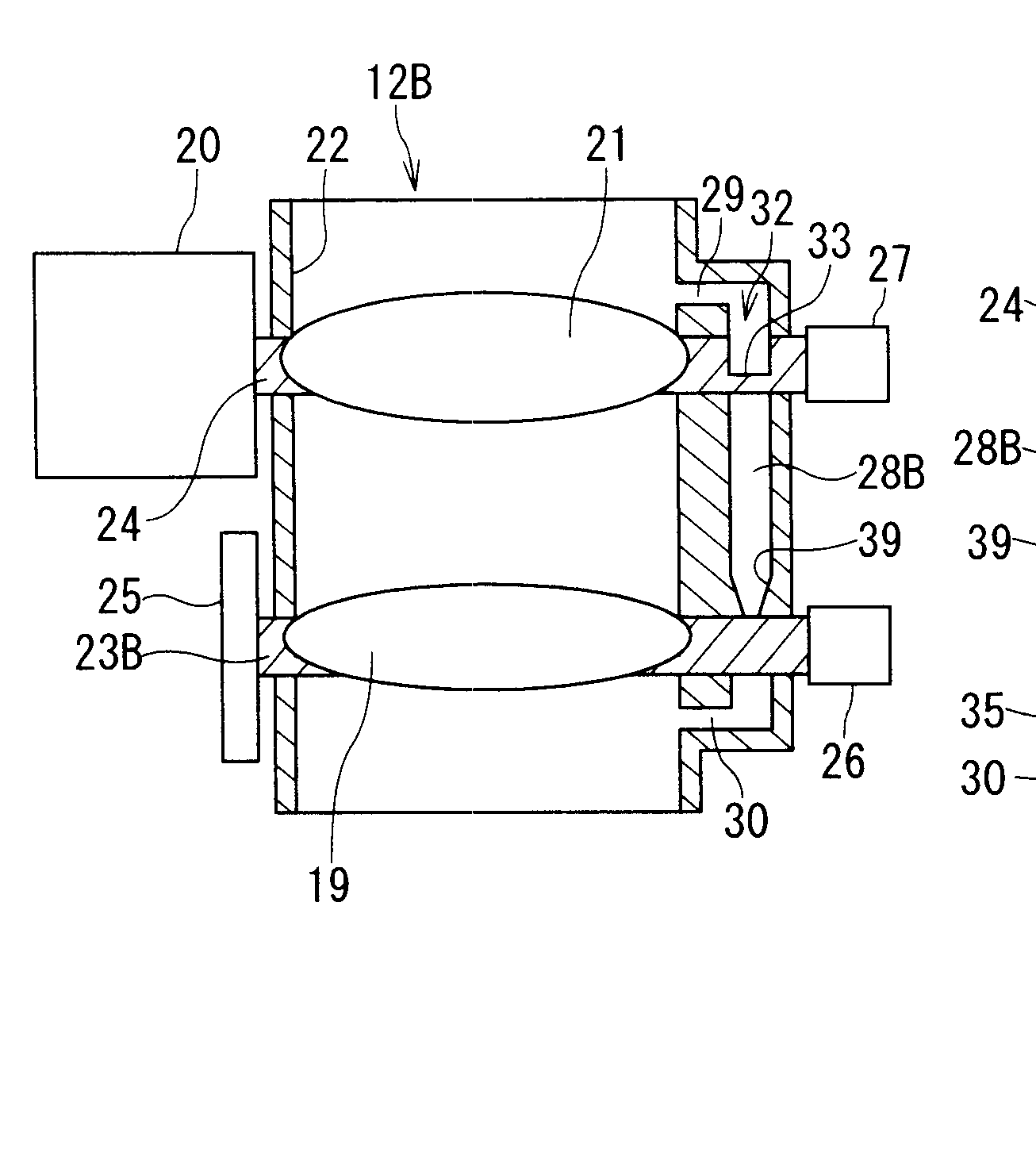
[0086]FIG. 11 is a schematic front view of a throttle body 12B according to the second embodiment of the present invention. FIG. 12 is a left-sided view thereof. FIG. 13 is a sectional view taken along the line XIII-XIII of FIG. 12. FIG. 14 is a sectional view taken along the line XIV-XIV of FIG. 11. The same components as those of the throttle body 12A of the first embodiment are denoted by identical reference numerals and description thereof is omitted.
[0087]As shown in FIGS. 11 to 14, the throttle body 12B includes the intake air path 22 extending vertically in figures. The intake air path 22 is provided with the main throttle valve 19 and the sub-throttle valve 21. The main thro...
second embodiment
[0090]Meanwhile, a bypass air path 28B is provided to the intake air path 22. The bypass air path 28B communicates with the bypass air inlet 29 formed in the wall of the throttle body 12B on the upstream side of the sub-throttle valve 21 and with the bypass air outlet 30 formed in the wall of the throttle body 12B on the downstream side of the main throttle valve 19 in the intake air path 22, for example. In the second embodiment, the bypass air path 28B is integrated with a side portion of the throttle body 12B or provided integrally therewith.
[0091]The bypass air inlet 29 is formed closer to and almost above the sub-valve shaft 24 as seen in a side view, while the bypass air outlet 30 is formed below the main valve shaft 23B at some distance therefrom as seen in a side view, and the bypass air path 28B is provided obliquely to cross the axial line 31 of the intake air path 22 as seen in a side view. The other end of the sub-valve shaft 24 extending toward the sub-throttle position...
PUM
 Abstract
Description
Claims
Application Information
 - R&D
- Intellectual Property
- Life Sciences
- Materials
- Tech Scout
- Unparalleled Data Quality
- Higher Quality Content
- 60% Fewer Hallucinations
Browse by: Latest US Patents, China's latest patents, Technical Efficacy Thesaurus, Application Domain, Technology Topic, Popular Technical Reports.
© 2025 PatSnap. All rights reserved.Legal|Privacy policy|Modern Slavery Act Transparency Statement|Sitemap|About US| Contact US: help@patsnap.com


