
Sulfur lamp having electrodes

a technology of sulfur lamps and electrodes, which is applied in the direction of discharge tubes/lamp details, discharge tubes luminescnet screens, gas-filled discharge tubes, etc., can solve the problems of inefficient light emission of incandescent lamps, short life, and simple and low-priced switching-on-light circuit of incandescent lamps, and achieve low energy transfer rate and high light emission efficiency.

Inactive Publication Date: 2009-06-02
LG ELECTRONICS INC
View PDF3 Cites 2 Cited by
  • Summary
  • Abstract
  • Description
  • Claims
  • Application Information

AI Technical Summary

Benefits of technology

The present invention provides an electrode sulfur lamp that has a high efficiency of emitting light and eliminates the need to use a short-lived magnetron. The lamp includes a transparent bulb with sulfur containing space and multiple electrodes, each inserted into the space and connected to a power supply. The sulfur is excited by an electric discharge to emit light. The technical effect of this invention is to improve the efficiency of light emission and reduce the need for a low-energy transfer rate magnetron.

Problems solved by technology

However, the incandescent lamp is inefficient in emitting light and has a short life.
Additionally, a switching-on-light circuit of the incandescent lamp is simple and low-priced.
However, the fluorescent light has a relatively large size when compared to the incandescent lamp.
The HID lamp is light-efficient and has a long life, but requires a relatively large amount of time between switching off and on light.
A problem with the conventional electrodeless sulfur lamp is that the life of magnetron is short-lived when compared to the quartz bulb.
However, the design life of the magnetrons are currently only about 15,000 to 20,000 hours.
The development in the magnetron generating the micro-wave is relatively slow, which contributes to lowering an energy transfer rate.

Method used


Image

  • Sulfur lamp having electrodes
  • Sulfur lamp having electrodes
  • Sulfur lamp having electrodes

Examples


Embodiment Construction

[0017]The particulars shown herein are by way of example and for purposes of illustrative discussion of the embodiments of the present invention only and are presented in the cause of providing what is believed to be the most useful and readily understood description of the principles and conceptual aspects of the present invention. In this regard, no attempt is made to show structural details of the present invention in more detail than is necessary for the fundamental understanding of the present invention, the description taken with the drawings making apparent to those skilled in the art how the several forms of the present is invention may be embodied in practice.

[0018]Reference will now be made in detail to the preferred embodiments of the present invention, examples of which are illustrated in the accompanying drawings.

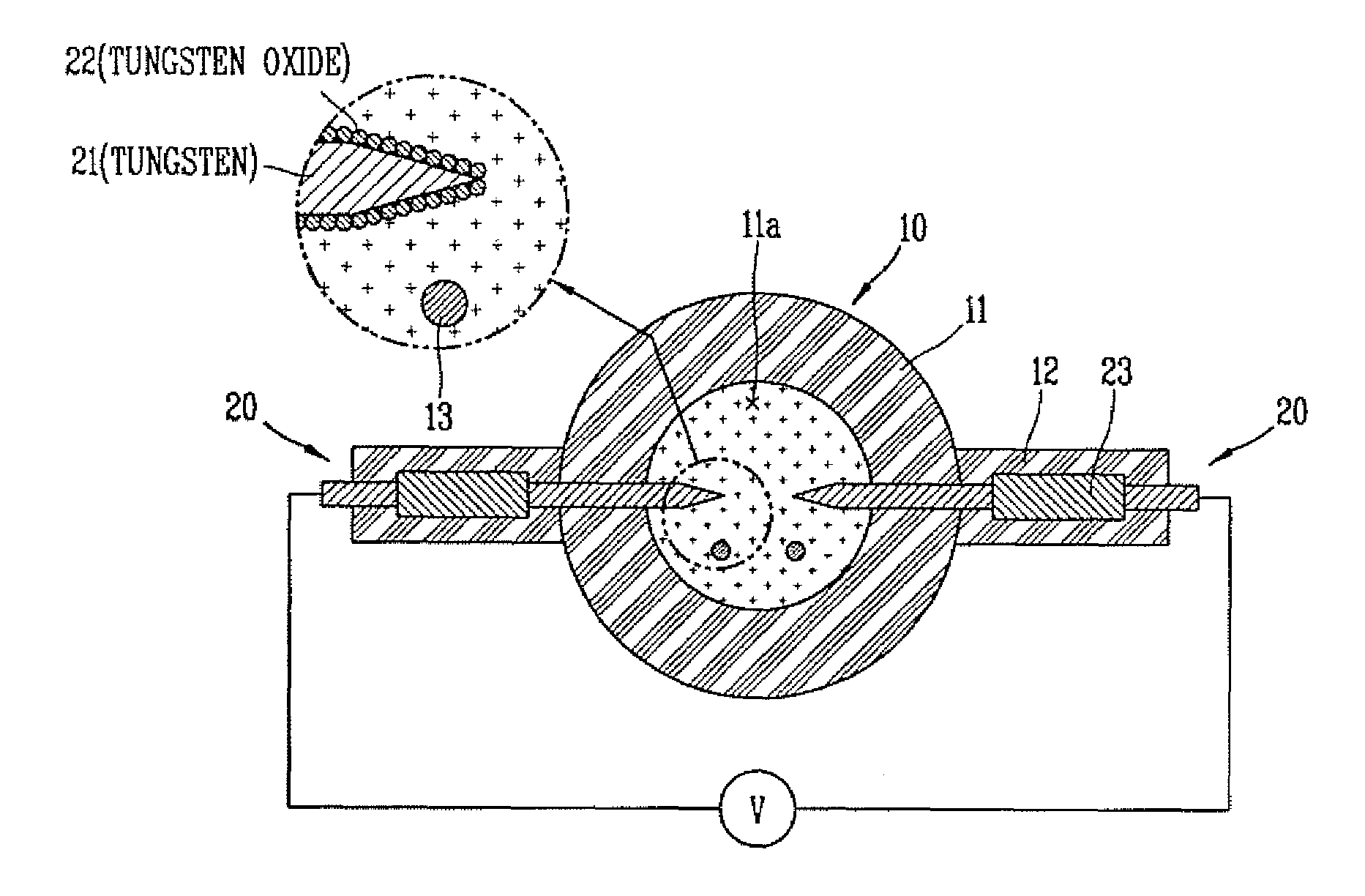
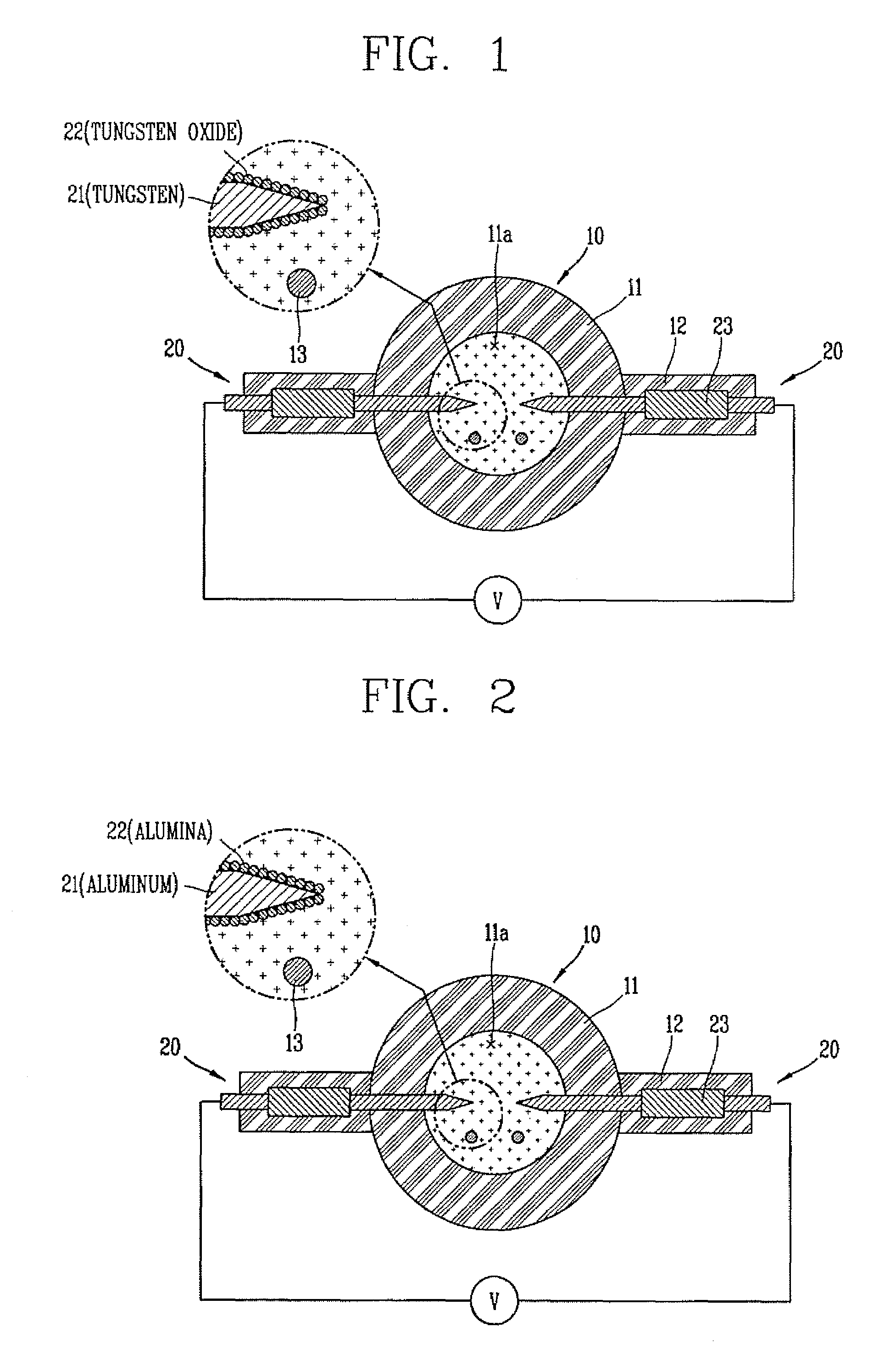
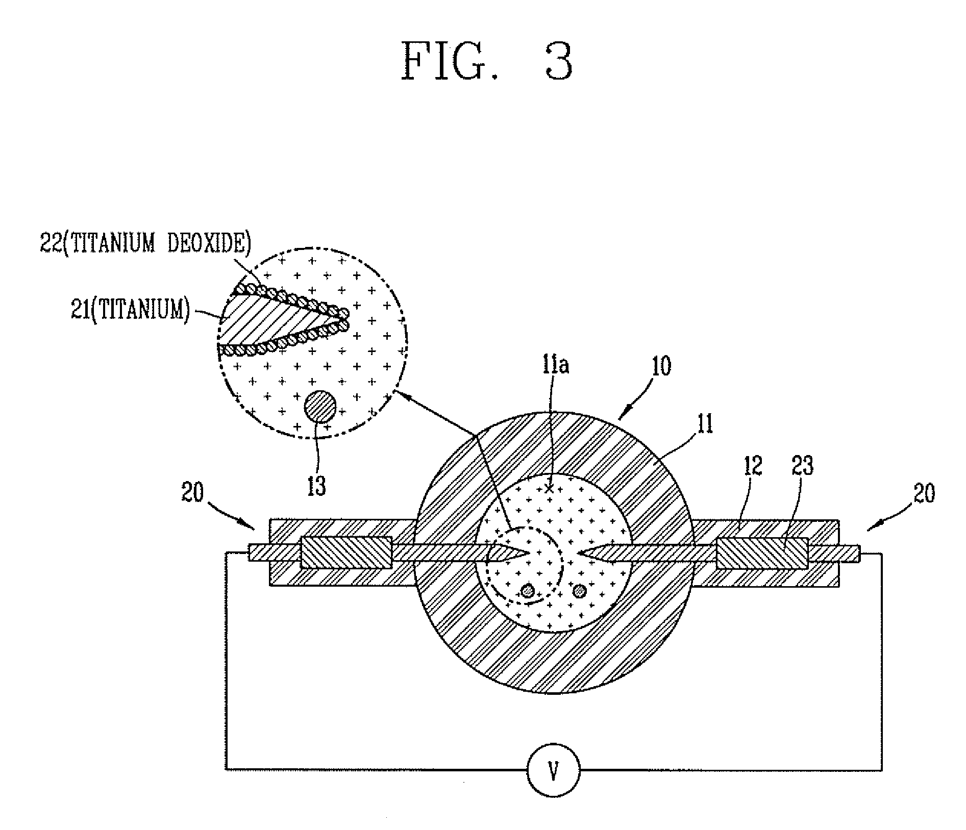
[0019]FIG. 1 is a cross-sectional view illustrating a sulfur lamp having metal electrodes according to a first non-limiting embodiment of the present invention...


PUM


Abstract

A sulfur lamp, is provided, including a power supply that supplies electrical power, a transparent bulb having a space inside that contains sulfur and a plurality of electrodes. Additionally, a portion of each electrode may be inserted into the space and an end of each electrode may be connected to the power supply such that the sulfur is excited by an electric discharge thereby emitting light. A portion of the electrode inserted into the space may be coated with a protective layer to prevent a chemical reaction of between the electrode and the sulfur. Further, the changing of the sulfur (contained in the space of the bulb) into a plasma phase may be accomplished by utilizing the electrodes (not microwaves). Therefore, a need to utilize a magnetron (which is low in energy transfer rate) may be eliminated, thereby increasing a system efficacy and saving a cost of replacing the magnetron.

Description

[0001]This application claims priority under 35 U.S.C. §119 to Korean Patent Application No. 2005-0092619, filed in Korea on Sep. 30, 2005, the entirety of which is hereby incorporated by reference.BACKGROUND OF THE INVENTION[0002]1. Field of the Invention[0003]The present invention relates to a sulfur lamp. More particularly, the present invention relates to a sulfur lamp having electrodes, which eliminate the need to use a magnetron.[0004]2. Description of the Background Art[0005]There are various sources of lighting, e.g., an incandescent lamp using heat radiation, a fluorescent lamp including an electric discharge tube that uses a fluorescent material, a high intensity discharge (HID) lamp that uses an electric discharge within a high-pressurized gas or steam, and a plasma lighting system (PLS) lamp that uses an electrodeless discharge.[0006]The various lamps have their respective advantages and disadvantages. For example, the incandescent lamp is excellent in color rendition an...

Claims


Application Information

Patent Timeline
Patent Type & Authority Patents(United States)
IPC IPC(8): H01J17/04
CPCH01J61/0732H01J61/0735H01J61/0737H01J61/12H01J61/82H01J65/046
Inventor PARK, BYEONG-JU
Owner LG ELECTRONICS INC
Learn More