
Vandal-resistant combination padlock

a combination padlock and anti-vandal technology, which is applied in the field of anti-vandal-resistant combination padlocks, can solve the problems of improving the safety drawback of conventional padlocks, and achieve the effect of significantly promoting the safety effect of the locked condition of the padlock

Active Publication Date: 2009-05-26
FEDERAL LOCK
View PDF8 Cites 17 Cited by
  • Summary
  • Abstract
  • Description
  • Claims
  • Application Information

AI Technical Summary

Benefits of technology

[0013]Accordingly, the object of the present invention is to provide a “vandal-resistant combination padlock” with feature that all the internal components in padlock are well protected to avoid from vandal unlocked manner suffered damage from external force or tool so that the safety effect of the locked condition for the padlock is significantly promoted.
[0020]For the “vandal-resistant combination padlock” aforesaid, wherein, a bore punched on the backside plate of the core and a corresponding hole punched on the rear side of the claw mount for being fixed together by a screw. From the disclosure above for the “vandal-resistant combination padlock” of the present invention, by setting claw mount in the core and attaching the ledge of the claw mount with the inner side of the lock body, the rocking claw is enclosed in the claw mount by the cantilevers and ledge as well as all the adjacent numerical dial wheels are inserted by the dividing ribs of the claw mount in between to avoid damage from external force or tool so that the safety effect of the locked condition for the padlock is significantly promoted.

Problems solved by technology

That is the safety drawback of the conventional padlock need to be improved.

Method used


Image

  • Vandal-resistant combination padlock
  • Vandal-resistant combination padlock
  • Vandal-resistant combination padlock

Examples


Embodiment Construction

[0029]For the technological means by the applicant of the present invention, an exemplary preferred embodiment in association with the relevant drawings is disclosed in the detailed description below for expediting your better understanding and recognition.

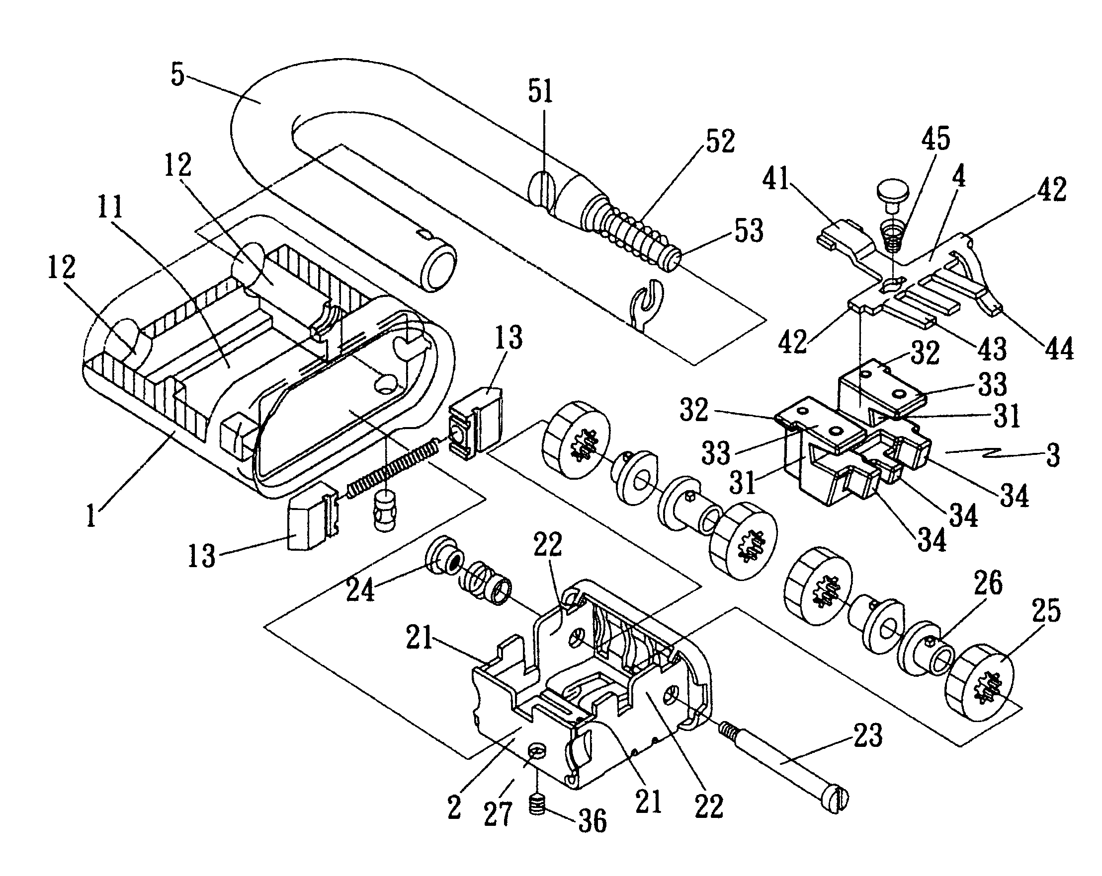
[0030]Please firstly refer to the FIGS. 5 and 6. The “vandal-resistant combination padlock” of the present invention comprises a lock body 1, a core 2, a claw mount 3, a locking claw 4 and an U-shaped locking shackle 5, wherein,

[0031]said lock body 1, which configures a cavity well 11 as shown in FIG. 5, has a pair of retaining holes 12 formed in the top surface and a pair of latching lumps 13 formed adjacent to the bottom section of the retaining holes 12;

[0032]said core 2, which located inside of the cavity well 11 with a pair of upper escutcheons 21 and a pair of lower escutcheons 22 attached thereon as shown in FIG. 5, has a shaft 23 and mating bushing collar 24 running through plural sets of numerical dial wheels 25 and coupl...


PUM


Abstract

A vandal-resistant combination padlock includes a lock body, a core, a claw mount, a locking claw and an U-shaped locking shackle. The lock body has a cavity well for containing a core and shackle. The core has plural sets of numerical dial wheels and coupling tumbler cams as well as a claw mount together with a rocking claw inserted therein. The rocking claw has a latching lever, plural pawls, a blocking dog and a clipping spring. The claw mount has a pair of cantilevers with each shoulder, a ledge and plural dividing ribs extended downwardly for inserting between the adjacent numerical dial wheels. By of the claw mount, the rocking claw is enclosed therein, the numerical dial wheels are properly inserted by the dividing ribs and all the internal components are well protected to avoid damage from an external force or tool.

Description

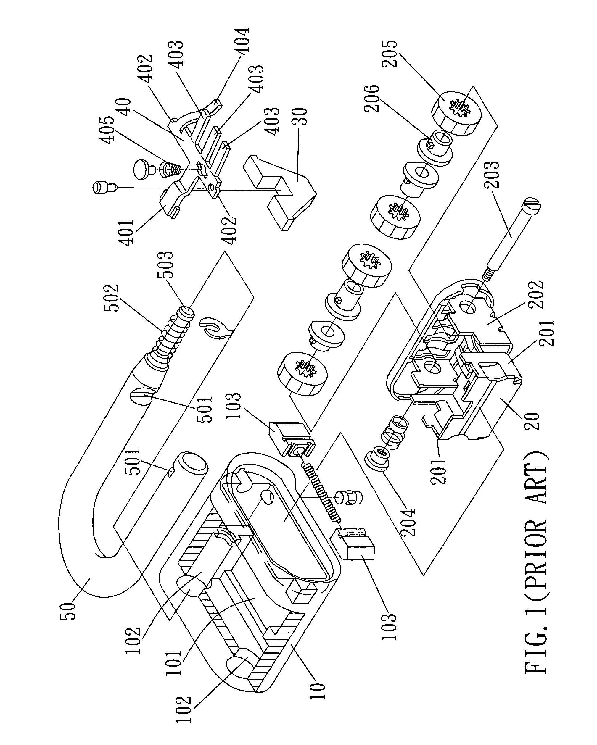
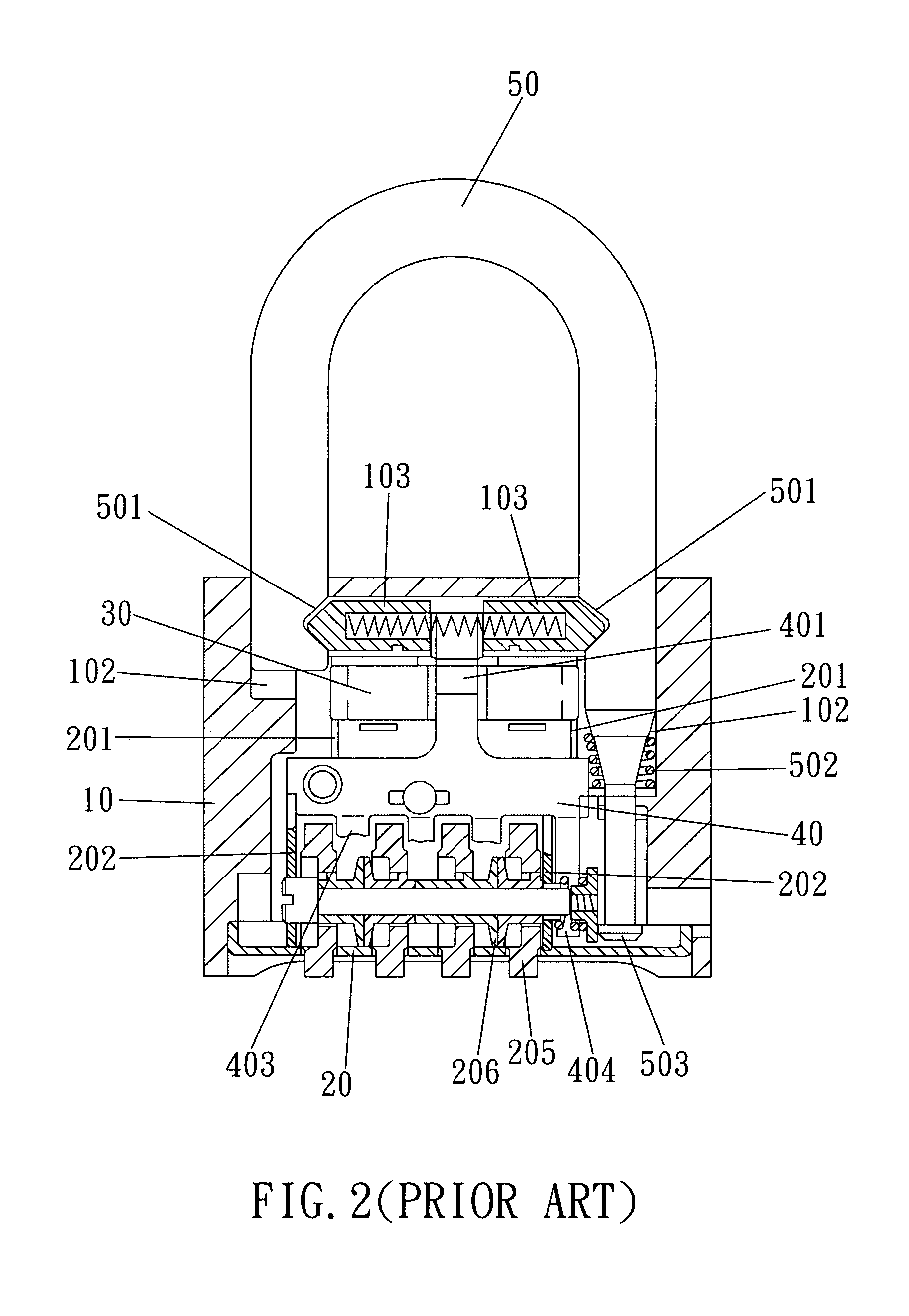
FIELD OF THE INVENTION[0001]The present invention relates to a “vandal-resistant combination padlock”, particularly for one having structural feature to enclose all the internal components therein being well protected to avoid damage from external force or tool so that the safety effect of the locked condition for the padlock is significantly promoted.BACKGROUND OF THE INVENTION[0002]For effective improvement the safety of the padlock to further protect the rights and interests, most of the industrial businessmen eagerly endeavor the research and development in the structural improvement of the padlock resulting into the current combination padlock from the evolution of non-combination padlock in the early stages. Other than the common combination padlock, some patented combination padlock with features of anti-vandal trait and easiness of operation are presented to the public in succession.[0003]Please refer to the FIGS. 1 and 2 for the perspective exploded view and the facade cros...

Claims


Application Information

Patent Timeline
Patent Type & Authority Patents(United States)
IPC IPC(8): E05B37/02
CPCE05B37/025Y10T70/424Y10T70/489Y10T70/7305Y10T70/7362
Inventor LIU, TIEN-KAO
Owner FEDERAL LOCK
Learn More