Transmitter circuit, receiver circuit, clock data recovery phase locked loop circuit, data transfer method and data transfer system
a technology of clock data and receiver circuit, applied in the field of clock data recovery phase locked loop circuit, transmitter circuit, receiver circuit, data transfer method and data transfer system, can solve the problem of no longer being able to recover accurate digital data, and achieve the effect of reducing errors occurring, eliminating the increase in the cost of the transfer system, and stable data transfer
- Summary
- Abstract
- Description
- Claims
- Application Information
AI Technical Summary
Benefits of technology
Problems solved by technology
Method used
Image
Examples
example 1
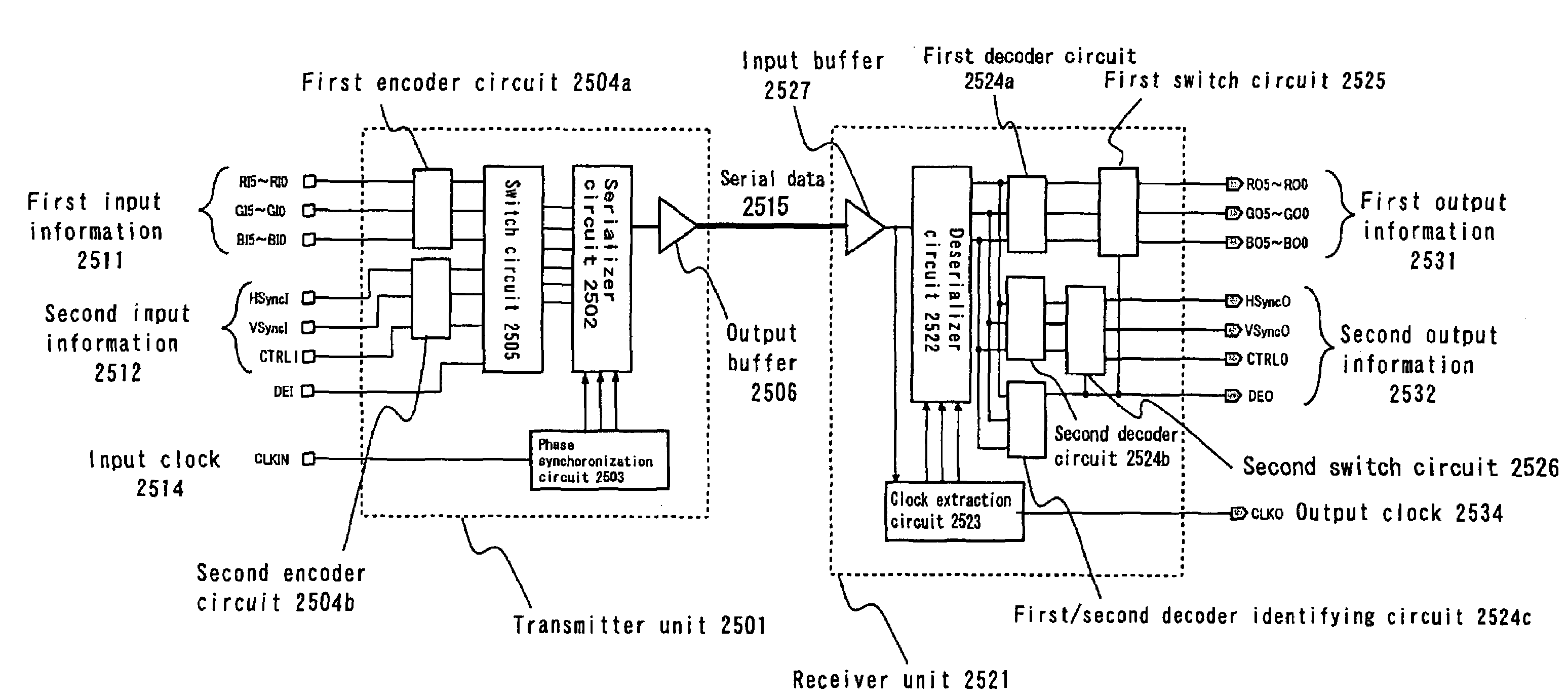
[0221]The present example is directed to an alternative example of the first encoder circuit 2504a in the digital data transfer system of the present invention as described in the embodiment above. Other elements are as described in the embodiment above, and will not be further described below.
[0222]Referring to FIG. 30, FIG. 30 is a diagram illustrating an example of a data error occurring in a serial transfer of digital data. In a data transfer system such as that of the present invention, serial digital data is transferred at a high speed via a pair of wires or cables. Therefore, when data is transferred over a long distance by increasing the wire length or the cable length, or when the wires or cables have poor characteristics, the waveform of the digital data may become smoothed, and bit errors are more likely to occur due to ISI (Intersymbol Interference). Such a data error is significant when low-level data is transferred after high-level data were being transferred for a whi...
example 2
[0230]Example 2 is an alternative example of the encoding method of the data transfer system described in the embodiment above. Other elements are as described in the embodiment above, and will not be further described below.
[0231]It is characteristic of the present example that the transmitter unit 2501 includes a DC balance circuit, and the encoding process is performed so as to ensure a DC balance of the serial data. The DC balance circuit counts the total number of “high”s (=1) and the total number of “low”s (=0) in the encoded data, and feeds back to the evaluation function a signal according to the counts. The feedback operation is for selecting encoding mode in the evaluation function so that the total number of “high”s (=1) and the total number of “low”s (=0) in the encoded data converge to the same number. The function of the DC balance circuit as described above will be referred to as a DC balance operation.
[0232]The encoding method in the data transfer system of the prese...
example 3
[0245]Example 3 is an alternative example of the clock data recovery phase locked loop circuit (clock extraction circuit) in the data transfer system of the embodiment described above.
[0246]Referring to FIG. 36, FIG. 36 is a hardware block diagram showing a circuit configuration of a clock data recovery phase locked loop circuit (clock extraction circuit) 2600 being a receiver circuit of the present invention. The clock extraction circuit 2600 of the present example is similar to the clock extraction circuit 2523 described in the embodiment above, but further includes a frequency comparison / fine adjustment circuit 80. The same elements as those described in the embodiment above will not be further described below.
[0247]The clock data recovery phase locked loop circuit 2600 of the present example includes the frequency comparison / fine adjustment circuit 80 for performing a finer frequency adjustment (fine frequency adjustment) of the voltage-controlled oscillator 30 after the frequen...
PUM
 Abstract
Description
Claims
Application Information
 - R&D
- Intellectual Property
- Life Sciences
- Materials
- Tech Scout
- Unparalleled Data Quality
- Higher Quality Content
- 60% Fewer Hallucinations
Browse by: Latest US Patents, China's latest patents, Technical Efficacy Thesaurus, Application Domain, Technology Topic, Popular Technical Reports.
© 2025 PatSnap. All rights reserved.Legal|Privacy policy|Modern Slavery Act Transparency Statement|Sitemap|About US| Contact US: help@patsnap.com


